Condensate water preventing type efficient kit drying device

A technology for preventing condensation water and drying equipment, which is applied to drying, drying machines, lighting and heating equipment, etc. The effect of saving consumption, extending relative time and improving drying efficiency

Inactive Publication Date: 2021-03-09
李银玲
View PDF0 Cites 6 Cited by
  • Summary
  • Abstract
  • Description
  • Claims
  • Application Information

AI Technical Summary

Problems solved by technology

[0003] Kits generally need to be dried before they can be put into use. However, the demand for kits in medical institutions is large, and it takes a long time for kits to dry naturally or manually. Therefore, drying equipment is usually needed to dry kits. When the existing kit drying equipment is drying, the drying speed is slow, and after drying, the humid air will contact the top of the drying box to form condensed water, which is easy to adhere to the kit again. As a result, the drying speed is slow, so we need to design an anti-condensation water-type high-efficiency kit drying equipment to solve the above problems

Method used


Image

  • Condensate water preventing type efficient kit drying device
  • Condensate water preventing type efficient kit drying device
  • Condensate water preventing type efficient kit drying device

Examples


Embodiment 1

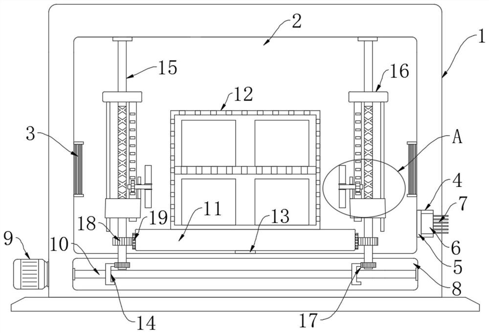
[0024] refer to Figure 1-2 , an anti-condensation water type high-efficiency kit drying equipment, comprising a drying box 1, a drying chamber 2 and a rotating chamber 8 are provided in the drying chamber 1, the rotating chamber 8 is located below the drying chamber 2, and the drying chamber 2, both sides inner wall is all equipped with heating resistance wire 3, heating resistance wire 3 is prior art, generates heat after electrification, is provided with placement frame 12 in drying chamber 2, placement frame 12 is made up of a plurality of perforated plates, each The manufacturing materials of each porous plate are heat-conducting materials, which are convenient to quickly transfer heat to the test kits, and multiple test kits are placed in the placement frame 12;

[0025] The energization mechanism, the energization mechanism includes a power generation tank 4 provided on the inner wall of one side of the drying chamber 2, a heat conduction plate 5 is fixedly connected to...

Embodiment 2

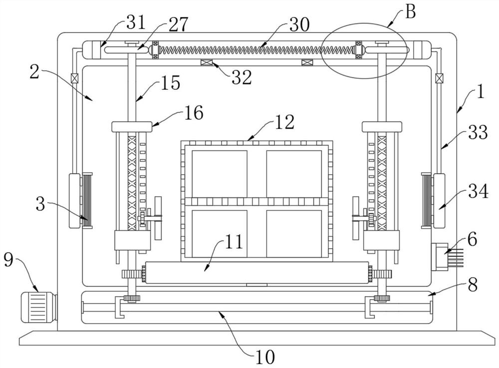
[0032] refer to Figure 3-4 , The difference between this embodiment and Embodiment 1 is that a movable cavity 26 is provided in the drying box 1, and the movable cavity 26 is located above the drying chamber 2, and the upper ends of the two vertical rods 15 all extend into the movable cavity 26 , the parts of the two vertical rods 15 located in the movable chamber 26 are provided with cams 27, and the movable chamber 26 is symmetrically provided with two baffles 28 for sliding left and right, and the two baffles 28 are located between the two cams 27 , the opposite ends of the two baffles 28 are elastically connected by springs 30, the opposite ends of the two baffles 28 are matched with the corresponding cams 27, the opposite ends of the two baffles 28 are fixedly connected with bumps, and the bumps Offset with the cam 27, the movable chamber 26 communicates with the drying chamber 2 through two inlet pipes 32, so as to absorb the gas in the drying chamber 2 into the movable...


PUM


Abstract

The invention discloses a condensate water preventing type efficient kit drying device. The condensate water preventing type efficient kit drying device comprises a drying box and an electrifying mechanism, wherein a drying chamber and a rotating cavity are formed in the drying box, the rotating cavity is located below the drying chamber, heating resistance wires are installed on the inner walls of the two sides of the drying chamber, a containing frame is arranged in the drying chamber, the containing frame is composed of a plurality of porous plates, a plurality of kits are placed in the containing frame, and the electrifying mechanism comprises a power generation groove formed in the inner wall of one side of the drying chamber. When the condensate water preventing type efficient kit drying device is used for drying the kits, heat generated by the heating resistance wires can be quickly dispersed in the drying chamber, humid air formed by water evaporation is treated at the same time, and therefore the kits can be quickly dried.

Description

technical field [0001] The invention relates to the field of kit drying, in particular to an anti-condensation water-type high-efficiency kit drying equipment. Background technique [0002] The kit is a box used to contain chemical reagents such as chemical components, drug residues, and virus types. It is generally used in hospitals and pharmaceutical companies. It is an important tool in medical equipment. The kit needs to carry various Samples, so the cleanliness of the kit will directly affect the test results, so the cleaning of the kit is very important; [0003] Kits generally need to be dried before they can be put into use. However, the demand for kits in medical institutions is large, and it takes a long time for kits to dry naturally or manually. Therefore, drying equipment is usually needed to dry kits. When the existing kit drying equipment is drying, the drying speed is slow, and after drying, the humid air will contact the top of the drying box to form conden...

Claims


Application Information

Patent Timeline
Patent Type & Authority Applications(China)
IPC IPC(8): F26B11/18F26B21/00F26B25/00F26B25/02F26B25/12F26B25/18
CPCF26B11/18F26B21/001F26B25/003F26B25/02F26B25/12F26B25/18
Inventor 李银玲袁贵雨
Owner 李银玲
Why Eureka
Try Eureka