Portable directional test antenna and using method thereof

A portable technology for testing antennas, applied in antennas, antenna supports/mounting devices, antenna grounding switch structural connections, etc., can solve problems such as low antenna gain, low positioning accuracy, and cumbersome operation processes, and achieve enhanced rigidity and stability Accuracy, reduction in measurement time, and reduced complexity

Pending Publication Date: 2021-03-09
CHINA XIAN SATELLITE CONTROL CENT
View PDF0 Cites 1 Cited by
  • Summary
  • Abstract
  • Description
  • Claims
  • Application Information

AI Technical Summary

Problems solved by technology

Hand-held positioning accuracy is low, the antenna gain is low, the detection range is low, the location of the interference source is not quantified, the troubleshooting test takes a long time, i

Method used


Image

  • Portable directional test antenna and using method thereof
  • Portable directional test antenna and using method thereof
  • Portable directional test antenna and using method thereof

Examples


Embodiment Construction

[0029] In May 2019, a c-band system in our unit found external electromagnetic interference at AZ: 285°, EL: 3°, which affected the equipment to track targets normally, locked downlink abnormalities, and telemetry data lost frames. Check and locate interference sources.

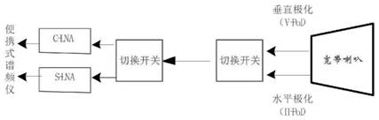
[0030] First, the technicians drive 15 kilometers according to the signal strength prediction, organize the preliminary orientation test of the interference source at the pre-selected point A, fix the portable orientation test antenna, and use the local area test method 7 to rotate the pitch adjustment handle (10) to Keep the antenna pitch pointing position at 3°, turn the azimuth hand wheel (12) back and forth, make the azimuth gear (18) mark point on the azimuth dial (11) 280°-290° slowly reciprocate, observe the signal on the portable spectrum analyzer The change of frequency spectrum, carry out the switching of polarization (5) and frequency band (7) through the combined switching of radio frequency switc...


PUM


Abstract

The invention relates to an antenna, in particular to a portable and detachable directional reflector antenna with directional coding quantization and a using method thereof, which can complete the adjustment of azimuth AZ: 360 degrees and pitch EL: -5-10 degrees. The antenna is mainly composed of an antenna/feed source structure, an orientation pitching combination and a telescopic foot stool, anorientation dial (11) and a pitching dial (15) clearly mark AZ and EL angles of the antenna along with actions of an orientation hand-operated wheel (12) and a pitching adjusting hand lever (10), orientation precision is accurate, meanwhile, a frequency band gain field amplifier (6) is matched, and high receiving sensitivity is achieved. The measurement time of secondary positioning and rotary repeated measurement is greatly shortened.

Description

[0001] Field [0002] The invention relates to an antenna, in particular to a portable, detachable, directional reflector antenna with directional coding and quantization, which can complete the adjustment of azimuth AZ: 360°, pitch EL: -5°~10°, and azimuth scale The dial (11) and the pitch dial (15) clearly mark the AZ and EL angles of the antenna with the azimuth hand wheel (12) and the pitch adjustment lever (10), and the orientation accuracy is accurate. (6) It has high receiving sensitivity, which greatly shortens the measurement time of secondary positioning and rotary re-measurement. Background technique [0003] The scheme of the present invention is mainly used for complex electromagnetic environment monitoring, direction finding and investigation of unknown transmitters and interference sources that affect the normal use of satellite measurement and control station equipment, and final positioning, interference avoidance or release. At present, interference test ante...

Claims


Application Information

Patent Timeline
IPC IPC(8): G01R31/00G01R1/02G01S7/40G01S19/21H01Q1/12H01Q1/24H01Q1/36H01Q1/50H01Q3/04H01Q15/14
CPCG01R1/02G01R31/001G01S7/40G01S7/4008G01S19/21H01Q1/12H01Q1/24H01Q1/36H01Q1/50H01Q3/04H01Q15/14
Inventor 王书宝白泽刚屈斌斌韩冰姚宏侯跳叶星赵玉柱
Owner CHINA XIAN SATELLITE CONTROL CENT
Why Eureka
Try Eureka