Outer rotor motor cooling structure

A technology of external rotor motor and cooling structure, which is applied in the direction of cooling/ventilation device, magnetic circuit shape/style/structure, electrical components, etc., and can solve the problems of increasing the difficulty of winding the motor winding off the assembly line, reducing the power density of the motor, and high motor processing technology and other issues to achieve the effect of improving cooling effect, reducing thermal resistance and improving heat dissipation capacity

Inactive Publication Date: 2021-03-12
QILU UNIV OF TECH
View PDF11 Cites 6 Cited by
  • Summary
  • Abstract
  • Description
  • Claims
  • Application Information

AI Technical Summary

Problems solved by technology

However, the heat pipe in this way occupies the space of the stator slot, which makes the slot full rate of the motor lower, which will increase the difficulty of winding the motor winding off the assembly line, requires higher motor processing technology, and will also lead to a significant drop in the power density of the motor.

Method used


Image

  • Outer rotor motor cooling structure
  • Outer rotor motor cooling structure
  • Outer rotor motor cooling structure

Examples


Embodiment Construction

[0025] In order to enable those skilled in the art to better understand the solution of the present invention, the present invention will be further described in detail below in conjunction with the accompanying drawings and specific embodiments.

[0026] In this article, terms such as "upper, lower, left, right, inner, outer" are established based on the positional relationship shown in the drawings, and the corresponding positional relationship may also change accordingly depending on the drawings, so , which cannot be understood as an absolute limitation on the scope of protection; moreover, relative terms such as "first" and "second" are only used to distinguish one from another part with the same name, while No such actual relationship or order between these components is necessarily required or implied. In addition, in the embodiments of the present invention, "above", "below", etc. include the original number.

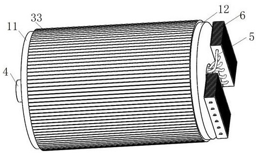
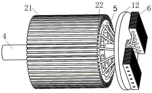
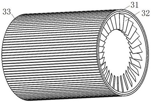
[0027] The cooling structure of the outer rotor motor dis...


PUM


Abstract

The invention belongs to the technical field of motors, and relates to an outer rotor motor cooling structure, which comprises a stator cooling assembly and a rotor cooling assembly, and is characterized in that the stator cooling assembly comprises a heat pipe mounted on a stator core close to a stator slot, one end of the heat pipe is positioned in a cooling hole of the stator core close to thestator slot; and the other end of the heat pipe is located in a cooling fin outside the motor end cover, and the rotor cooling assembly comprises a rotor fan located at the end part of the rotor core.The outer rotor motor cooling structure has the advantage that the cooling effect on the motor stator and rotor can be improved on the basis of not obviously increasing the motor machining process difficulty and the manufacturing cost.

Description

technical field [0001] The invention belongs to the technical field of motors and relates to a cooling structure of an outer rotor motor. Background technique [0002] In the occasions where belt conveyors are needed in industrial and mining enterprises, vehicle and ship docks, etc., the traditional driving method for belt conveyors is an asynchronous motor with a reducer to achieve low speed and high torque. This kind of drive has low efficiency, heavy maintenance workload and high operating cost. With the rapid development of permanent magnet motors and their drive control, low-speed high-torque direct-drive permanent magnet motors have been developed and rapidly promoted. They are gradually replacing traditional asynchronous motors in industrial, mining, wharf and other occasions to achieve high efficiency and high efficiency of the drive system. Direct drive, energy saving and other good effects. Among them, the outer rotor low-speed high-torque permanent magnet drum d...

Claims


Application Information

Patent Timeline
Patent Type & Authority Applications(China)
IPC IPC(8): H02K1/20H02K5/18H02K9/06
CPCH02K1/20H02K5/18H02K9/06
Inventor 孙明灿
Owner QILU UNIV OF TECH
Why Eureka
Try Eureka