
Photovoltaic power generation system for smart agriculture

A photovoltaic power generation system and agricultural technology, applied in photovoltaic power generation, photovoltaic modules, solar thermal power generation, etc., can solve the problems of single energy capture method, large power consumption, and low power generation rate, so as to improve photoelectric conversion efficiency and light intensity , the effect of improving the utilization rate of light

Active Publication Date: 2021-03-12
云南众远电力工程有限公司
View PDF6 Cites 0 Cited by
  • Summary
  • Abstract
  • Description
  • Claims
  • Application Information

AI Technical Summary

Problems solved by technology

With the development of agricultural science and technology, more and more high-tech equipment and machinery are used in agricultural production. The rapid development of agriculture in my country also has extremely prominent problems. The energy consumption of agricultural production remains high. Solar photovoltaic power generation as The important way of solar energy utilization has a very broad development prospect, but the current energy capture method is too single and the utilization rate is low, and the power generation rate is low. Large-scale smart agricultural greenhouses have exhaust systems, humidity control systems, and lighting systems. It consumes a lot of electricity, and it is necessary to build power supply facilities from places with electricity to smart agricultural greenhouses, which requires a large economic investment, and the benefits are relatively reduced. If solar energy is applied to agricultural greenhouses, these expenses can be reduced. To this end, we propose a photovoltaic power generation system for smart agriculture

Method used


Image

  • Photovoltaic power generation system for smart agriculture
  • Photovoltaic power generation system for smart agriculture
  • Photovoltaic power generation system for smart agriculture

Examples


Embodiment Construction

[0021] The following will clearly and completely describe the technical solutions in the embodiments of the present invention with reference to the accompanying drawings in the embodiments of the present invention. Obviously, the described embodiments are only some, not all, embodiments of the present invention. Based on the embodiments of the present invention, all other embodiments obtained by persons of ordinary skill in the art without making creative efforts belong to the protection scope of the present invention.

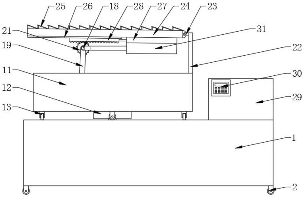
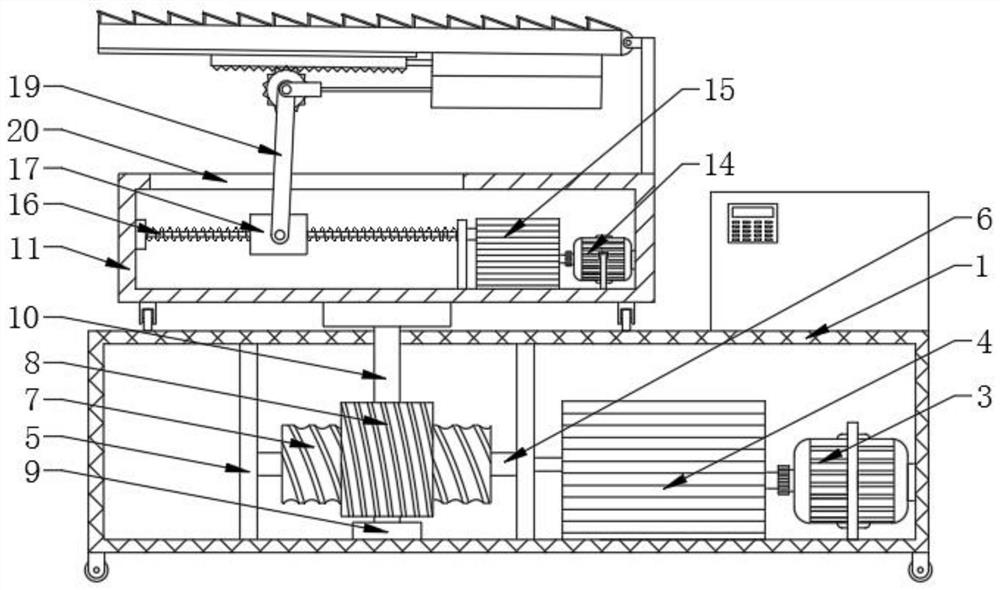
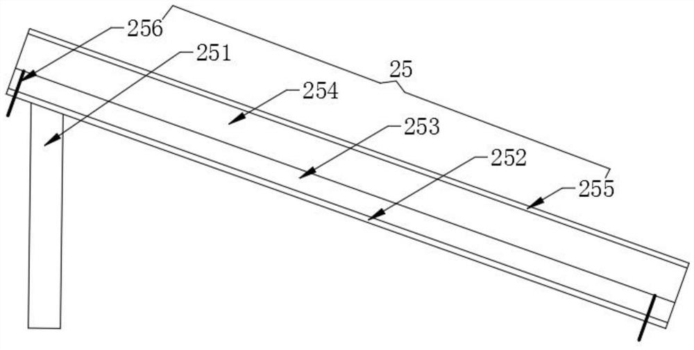
[0022] see figure 1 and figure 2, the present invention provides a technical solution: a photovoltaic power generation system for smart agriculture, including a first protection box 1, universal rollers 2 are fixed at the four corners of the bottom of the first protection box 1, and the first protection box 1 A first servo motor 3 is fixed at the bottom right side of the inner cavity, the output end of the first servo motor 3 is fixedly equipped with a first...


PUM


Abstract

The invention discloses a photovoltaic power generation system for smart agriculture in the technical field of photovoltaic power generation systems for smart agriculture, and the system is characterized in that the outer wall of a rotating shaft is fixedly sleeved with a worm, a bearing support is movably provided with a worm wheel engaged with the worm, and the outer wall of the screw is provided with a threaded sliding cylinder in a screwed manner; a supporting pull rod is hinged to the front side wall of the threaded sliding cylinder through a rotating pin shaft, a rack and a gear are assembled in a meshed mode, a control panel is fixed to the front side wall of the light energy conversion power storage box, and a second electric push rod is fixed to the bottom of the first electric push rod; and the output end of the second electric push rod is fixedly assembled on the outer wall of a rotating pin shaft on a gear through a bracket, and the inclination angle and the horizontal angle of the mounting plate can be independently and complementarily adjusted, so that the azimuth angle of the solar photovoltaic module on the mounting plate can be increased, the solar photovoltaic module can better absorb sunlight, and light conversion efficiency is increased.

Description

technical field [0001] The invention relates to the technical field of photovoltaic power generation systems for smart agriculture, in particular to a photovoltaic power generation system for smart agriculture. Background technique [0002] Smart agriculture is the application of Internet of Things technology to traditional agriculture, using sensors and software to control agricultural production through mobile platforms or computer platforms, making traditional agriculture more "smart". In addition to precise perception, control, and decision-making management, in a broad sense, smart agriculture also includes agricultural e-commerce, food traceability and anti-counterfeiting, agricultural leisure tourism, and agricultural information services. With the development of agricultural science and technology, more and more high-tech equipment and machinery are used in agricultural production. The rapid development of agriculture in my country also has extremely prominent proble...

Claims


Application Information

Patent Timeline
Patent Type & Authority Applications(China)
IPC IPC(8): H02S20/32F24S30/45F24S50/20
CPCH02S20/32F24S30/45F24S50/20Y02E10/50
Inventor 陈有海徐清朝孙继东尹正权白玉娇
Owner 云南众远电力工程有限公司
Learn More