Swather

A technology for windrowers and headers, applied in the direction of harvesters, headers, cutters, etc., can solve the problems of complex adjustment structure, influence of rotating parts, and potential safety hazards, and achieve reasonable structure of the transmission system, avoiding sagging and swinging. , the effect of reducing energy consumption

Pending Publication Date: 2021-03-16
CHONGQING DINKING POWER MACHINERY +1
View PDF0 Cites 2 Cited by
  • Summary
  • Abstract
  • Description
  • Claims
  • Application Information

AI Technical Summary

Problems solved by technology

[0004] (1) The armrest frame is the main component of the windrower, but most of the existing armrest frames cannot be adjusted, or the armrests on the left and right sides can only be adjusted synchronously, which cannot meet the individual needs of different operators. At the same time, the adjustment structure is complicated. Not easy to arrange
[0005] (2) As the core component of the windrowing machine, the header needs to be adjusted up and down in order to adapt to harvesting of different types and heights of crops. It is inconvenient to operate and has great limitations.
Because the existing windrower is not equipped with a clutch mechanism, when the engine is rotating, the header is always in working condition, resulting in waste of power and potential safety hazards
[0007] In addition, the drive of the existing header mainly depends on the universal joint. Since the universal joint is long and has a large rotation radius, it takes up a relatively large space, and the universal joint will cause damage to the crops during the rotation and swing process, and it is easy to Winding Causes Malfunction
[0008] (4) The belt drive mechanism is used to transmit the power of the engine to the header and the wheels, but the safety of the belt drive is low, and th

Method used


Image

  • Swather
  • Swather
  • Swather

Examples


Embodiment Construction

[0048] Below by embodiment and in conjunction with accompanying drawing, the present invention will be further described:

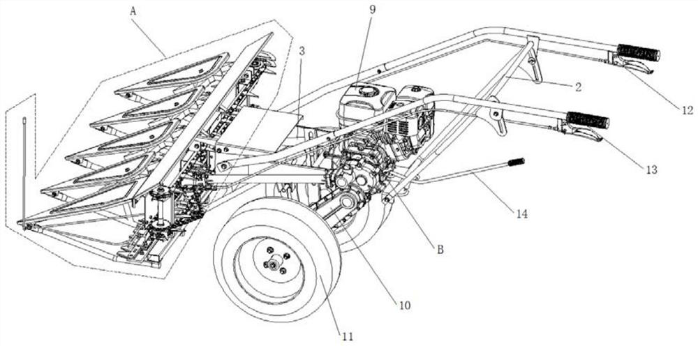
[0049] Such as figure 1 As shown, a windrower is mainly composed of engine 9, main transmission system B, main frame 3, walking box 10, armrest frame, support frame 2, header A, wheels 11, main clutch control handle 12, header clutch The control handle 13 and the shift lever 14 are composed. Header A is installed in the place ahead of main frame 3, and wheel 11 is positioned at the rear bottom of main frame 3, and two wheels 11 link to each other by wheel axle 15.

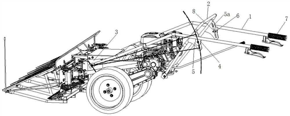
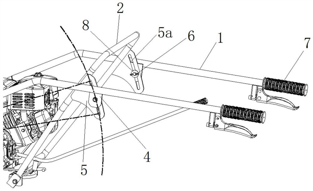
[0050] combine figure 2 , image 3 As shown, the armrest frame is divided into left and right two armrest bars 1, and the two armrest bars 1 are arranged separately, and are equipped with independent adjustment mechanisms to carry out respective lifting adjustments.

[0051] The support frame 2 is centrally arranged between two handrail bars 1, and the front end of each handrail bar 1 is ...


PUM


Abstract

The invention discloses a swather which comprises an engine, a main transmission system, a main rack, a walking box, an armrest frame, a supporting frame, a header, wheels, a main clutch control handle, a header clutch control handle and a gear shifting rod. The main transmission system is connected with a header driving mechanism through a transmission shaft, the header driving mechanism comprises a header clutch assembly, an eccentric arm assembly and a driving disc, and the clutch assembly comprises a driving shaft, a header clutch arm, a clutch bevel gear, a header transmission shaft, a transmission bevel gear and a first clutch claw. Independent lifting adjustment of a left armrest and a right armrest can be realized, so that individual requirements of different operators can be met;the structure of header lifting adjustment is simplified, so that the header lifting adjustment is more convenient and faster; header driving has a clutch function, and the wheels can independently walk; the transmission structure of a main transmission mechanism is changed to improve the transmission efficiency; and the problems of drooping and swinging of a large-span chain wheel and chain conveying mechanism of the header are avoided.

Description

technical field [0001] The invention relates to the technical field of agricultural machinery, in particular to a windrower. Background technique [0002] The harvesting and drying of straw crops such as rice, wheat, and cotton requires a lot of resources and manpower, and the efficiency is not high. As modern agriculture tends to be large-scale, large-scale, and mechanized, the windrowing machine came into being. [0003] The windrower is a kind of mechanical equipment that cuts crops and lays them flat in the field. It has very high production efficiency and is easy to use. Compared with large-scale agricultural machinery, the windrower has the advantages of small size, light weight, and flexible use. But existing windrower mainly has the following problems: [0004] (1) The armrest frame is the main component of the windrower, but most of the existing armrest frames cannot be adjusted, or the armrests on the left and right sides can only be adjusted synchronously, which...

Claims


Application Information

Patent Timeline
IPC IPC(8): A01D34/10A01D34/40A01D34/30A01D69/06A01D69/08A01D47/00A01D57/00
CPCA01D34/10A01D34/30A01D34/40A01D47/00A01D57/00A01D69/06A01D69/08
Inventor 张学义邓山山
Owner CHONGQING DINKING POWER MACHINERY
Why Eureka
Try Eureka