Leg drilling device for orthopedic treatment use

A punching device and leg technology, which are applied in application, medical science, bone drill guidance, etc., can solve the problems of insufficient punching accuracy, inconvenient treatment work, and inability to accurately understand the speed at which the drill bit descends. Accurate, accurate punch location and quick results

Inactive Publication Date: 2021-03-16
张宏伟
View PDF0 Cites 0 Cited by
  • Summary
  • Abstract
  • Description
  • Claims
  • Application Information

AI Technical Summary

Problems solved by technology

[0003] In the existing treatment process, most of the holes are punched manually, and the punching accuracy is not enough
And the existing mechanical equipment for punching cannot accurately understand the speed at which the drill bit descends when punching holes, which brings inconvenience to the treatment work and cannot make the punching position more accurate and fast;

Method used


Image

  • Leg drilling device for orthopedic treatment use
  • Leg drilling device for orthopedic treatment use
  • Leg drilling device for orthopedic treatment use

Examples


Embodiment 1

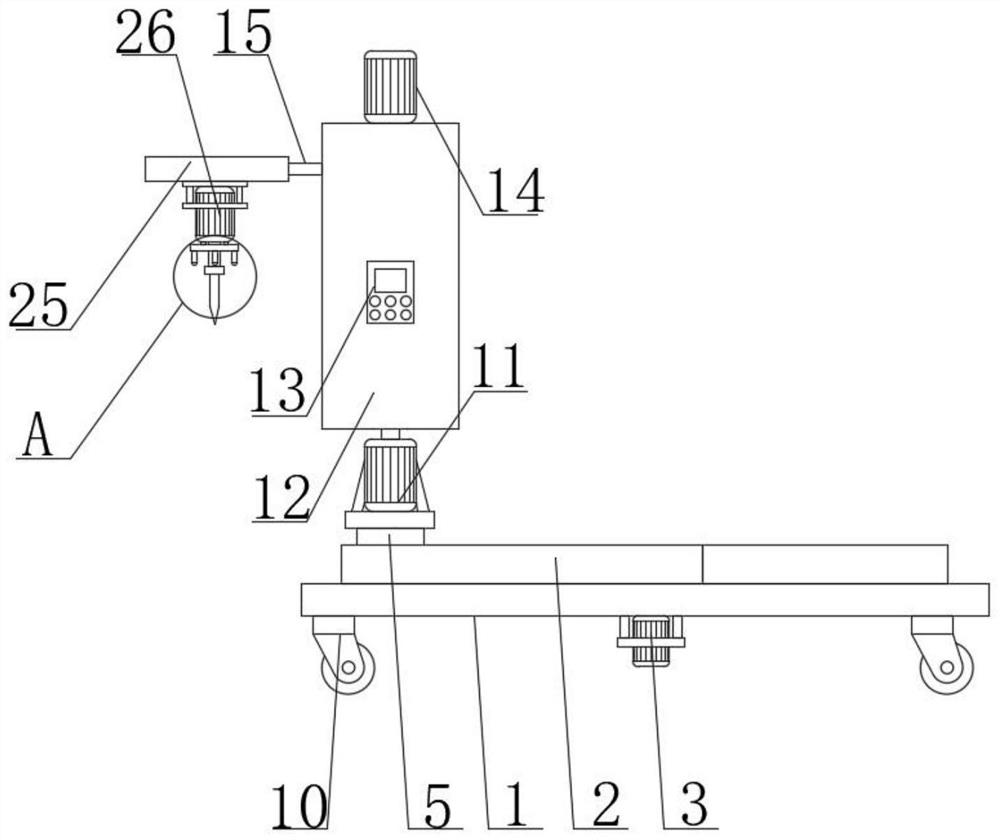
[0027] see figure 1 , figure 2 , Figure 4 and Figure 5 , a leg punching device for orthopedic treatment, a leg punching device for orthopedic treatment, comprising a base 1; a first housing 2; a second housing 12; and a drilling motor 26; on the base 1 The first housing 2 is fixedly connected, and the first housing 2 is connected with the second housing 12 through an adjustment mechanism; the second housing 12 is rotatably connected with a threaded rod 24, and the threaded rod 24 wears After passing through the second housing 12, it is fixedly connected with the output shaft of the third motor 14, and the third motor 14 is fixedly connected on the second housing 12; the threaded rod 24 is threaded with a nut block 21, and the The nut block 21 is fixedly embedded in the lifting block 20; one end of the lifting block 20 is rotatably connected to the second gear 17 through the mounting base 18, and the speed sensor 19 is fixedly connected to the mounting base 18, and the sp...

Embodiment 2

[0038]As a preferred solution of Embodiment 1, please refer to figure 1 , Figure 6 and Figure 7 , the adjustment mechanism includes a slider 4, a first rack 8 and a second motor 11, the slider 4 is slidably connected in the first housing 2, and one end of the slider 4 is symmetrically fixedly connected with two The first rack 8, two first gears 9 are symmetrically rotatably connected in the first housing 2, and the two first gears 9 mesh with each other; the bottom end of the base 1 is also fixedly connected with a first Motor 3, and the output shaft of the first motor 3 passes through the first housing 2 and is coaxially fixedly connected with the first gear 9; the top of the slider 4 is fixedly connected with the second motor 11 through the connecting column 5, so The connecting column 5 is slidably connected to the first housing 2 through the sliding opening 30, and the output shaft of the second motor 11 is fixedly connected to the second housing 12; the second motor 1...

Embodiment 3

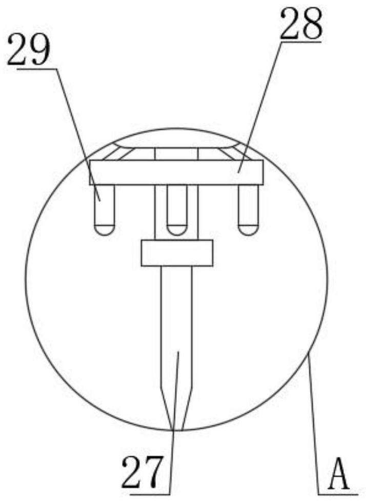
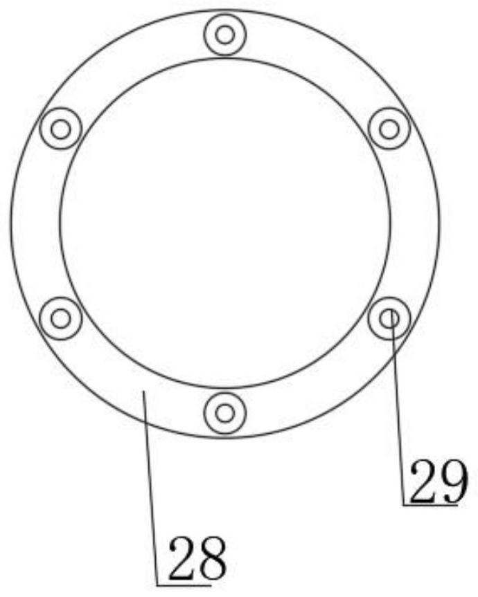
[0048] As a preferred solution of Embodiment 1 or Embodiment 2, please refer to figure 1 , figure 2 and image 3 , the bottom end of the drilling motor 26 is also fixedly connected with a fixed ring 28, and the fixed ring 28 is located at the outer end of the output shaft of the drilling motor 26, and the bottom end of the fixed ring 28 is uniformly fixedly connected with several Laser pointer 29;

[0049] Wherein, the laser pointer 29 can emit laser lines;

[0050] Working principle: when the drill bit 27 descends, by starting the laser pointer 29, the rays emitted by several laser pointers 29 form a circular ring-shaped structure, and then align the circular ring-shaped structure with the center position of the patient to be punched, and then When drilling through the drill bit 27, the position to be drilled is set at the center of the circular ring structure formed by the laser line, so that the drill bit 27 can be drilled more accurately.


PUM


Abstract

The invention relates to a leg drilling device for orthopedic treatment use. The leg drilling device for the orthopedic treatment use comprises a base, a first housing, a second housing, and a drilling motor; the first housing is fixedly connected to the base, and is connected with a second housing through an adjusting mechanism; a threaded rod is rotatably connected into the second housing, penetrates through the second housing, and fixedly connected with an output shaft of a third motor; the third motor is fixedly connected to the second housing; and nut block is in threaded connection withthe threaded rod. When a lifting block drives a drill bit to move downwards, a second gear rotates on a second rack so that the rotating speed of the second gear can be detected by a speed sensor; andthen, the rotating speed information is displayed on a display screen of a controller in a data mode, so that the descending speed of the lifting block and the descending speed of a drilling motor can be observed. Thus, the descending speed of the drill bit in the leg can be obtained at any time, thereby facilitating treatment work.

Description

technical field [0001] The invention relates to the field of medical devices, in particular to a leg punching device for orthopedic treatment. Background technique [0002] Orthopedics is one of the most common departments in major hospitals. It mainly studies the anatomy, physiology and pathology of the musculoskeletal system, and uses drugs, surgery and physical methods to maintain and develop the normal shape and function of this system; fracture refers to the continuity of bone structure. Completely or partially broken. When the bones are subjected to a great external force, such as: impact, falling from a height, car accident, etc., the bones will cause great damage, resulting in fractures. The method often used to treat fractures is to implement bone distraction surgery. During bone distraction surgery, it is necessary to punch the bone at the fracture site, and then perform bone needle puncture; [0003] In the existing treatment process, most of the holes are punch...

Claims


Application Information

Patent Timeline
Patent Type & Authority Applications(China)
IPC IPC(8): A61B17/17A61B17/16A61B90/00
CPCA61B17/16A61B17/1626A61B17/17A61B90/06
Inventor 张宏伟
Owner 张宏伟
Why Eureka
Try Eureka