Gas leakage detection method and system

A leak detection and gas technology, applied in the field of gas leak detection methods and systems, can solve problems such as unfavorable long-distance imaging, low signal-to-noise ratio, etc., and achieve the effects of short response time, low dark noise, and avoiding losses and hazards.

Pending Publication Date: 2021-03-16
SHENZHEN INST OF ADVANCED TECH CHINESE ACAD OF SCI
View PDF0 Cites 0 Cited by
  • Summary
  • Abstract
  • Description
  • Claims
  • Application Information

AI Technical Summary

Problems solved by technology

However, the smaller the pixel of the image sensor, the fewer photons it collects, resultin

Method used


Image

  • Gas leakage detection method and system
  • Gas leakage detection method and system

Examples


Embodiment

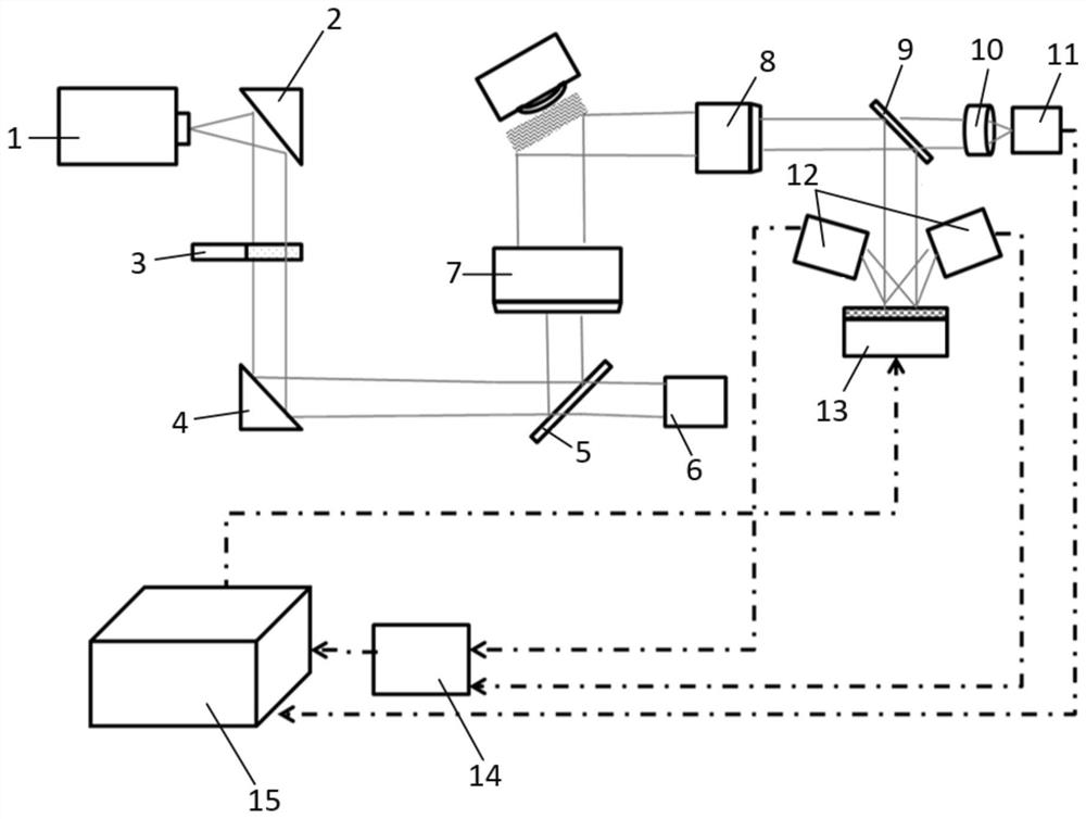
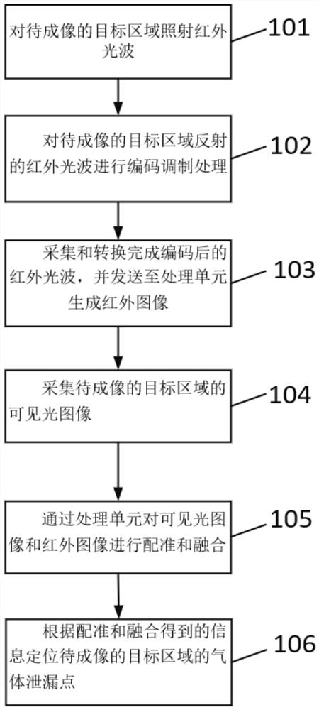
[0075] Such as Figure 1-Figure 2 As shown, the present embodiment provides a gas leak detection method, comprising:

[0076] Set the appropriate long-wave infrared laser power according to the distance of the target area, use the infrared illumination unit to illuminate the target area to be imaged with infrared light waves, and perform encoding and modulation processing on the infrared light waves reflected by the target area to be imaged. The encoded infrared light wave is collected and converted, and sent to the processing unit 15 to generate an infrared image, and at the same time, a visible light image of the target area to be imaged is collected. The visible light image and the infrared image are registered and fused by the processing unit 15, and the gas leakage point of the target area to be imaged is located according to the information obtained by the registration and fusion.

[0077] In this embodiment, "Using the infrared illumination unit to irradiate the target...


PUM


Abstract

The invention provides a gas leakage detection method and system. The gas leakage detection method comprises the steps of: using an infrared lighting unit for irradiating infrared light waves to a target region to be imaged; performing coding modulation processing on infrared light waves reflected by the target region to be imaged; collecting and converting the coded infrared light waves, and sending the coded infrared light waves to a processing unit to generate an infrared image; collecting a visible light image of the target region to be imaged; registering and fusing the visible light image and the infrared image through using a processing unit; and positioning a gas leakage point of the target region to be imaged according to the information obtained by registration and fusion. According to the gas leakage detection method, intensity values of the coded and modulated infrared light waves are collected based on two single-pixel detectors and transmitted to the processing unit to generate the infrared image, the gas leakage point of the target region to be imaged can be accurately and rapidly positioned through using target information generated by registration and fusion of thevisible light image and the infrared image by the processing unit, and an alarm is given in time, so that loss and harm caused by gas leakage are avoided.

Description

technical field [0001] The present invention relates to the technical field of gas leak detection, in particular to a gas leak detection method and system. Background technique [0002] At present, the existing gas infrared imaging leak detection products in the domestic and foreign markets are mainly based on two different detection technologies, namely infrared laser imaging and infrared thermal imaging detection technology. These products mainly detect the infrared characteristic signal generated by gas radiation (or absorption), convert the signal into an image that can be distinguished by human vision, and combine with optical filters to realize the identification of specific gases. [0003] However, infrared laser imaging sensors have limited sensitivity and are difficult to detect micro-leakage; the structure is complex and bulky, inconvenient to use, and requires high detection background. In order to improve sensitivity, high-power infrared lasers are often used, so...

Claims


Application Information

Patent Timeline
IPC IPC(8): G01N21/47G01M3/04
CPCG01M3/04G01N21/4738G01N21/474G01N2021/4769
Inventor 刘文权张锐董玉明鲁远甫佘荣斌祝永乐
Owner SHENZHEN INST OF ADVANCED TECH CHINESE ACAD OF SCI
Why Eureka
Try Eureka