Method for computer-implemented simulation of LIDAR sensor in virtual environment

A virtual environment and sensor technology, applied in computing, 3D image processing, instruments, etc., can solve the problems of high risk and high cost of accidents, and achieve the effect of simplifying evaluation and saving computing resources

Pending Publication Date: 2021-03-19
FORD GLOBAL TECH LLC
View PDF1 Cites 0 Cited by
  • Summary
  • Abstract
  • Description
  • Claims
  • Application Information

AI Technical Summary

Problems solved by technology

However, this is an expensive process and carries a high risk of accidents

Method used


Image

  • Method for computer-implemented simulation of LIDAR sensor in virtual environment
  • Method for computer-implemented simulation of LIDAR sensor in virtual environment
  • Method for computer-implemented simulation of LIDAR sensor in virtual environment

Examples


Embodiment Construction

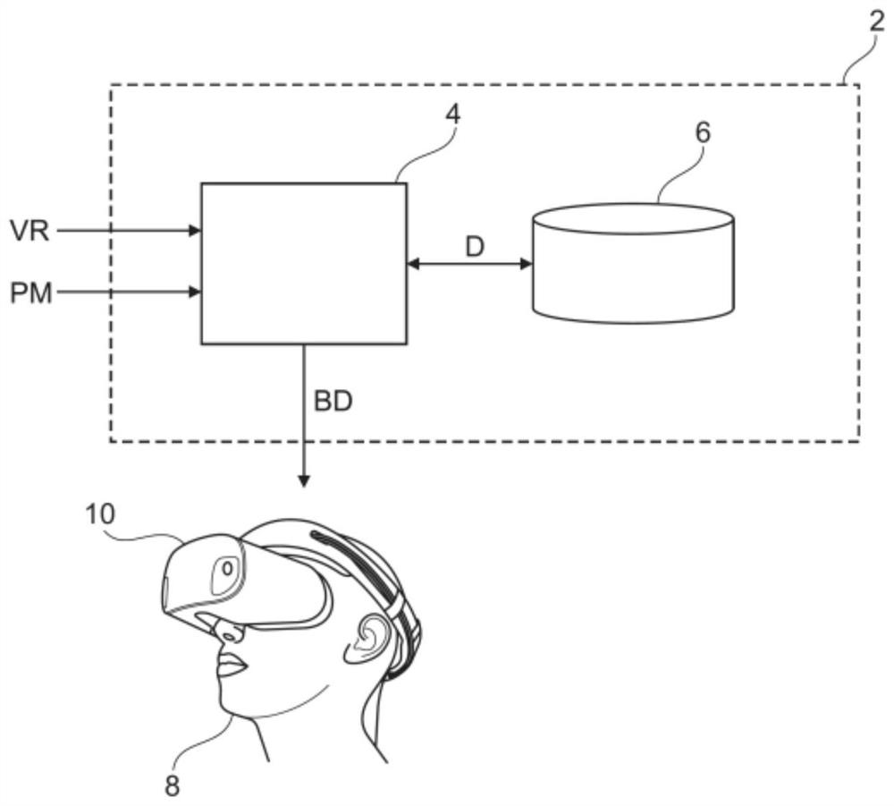
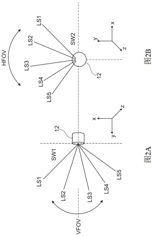
[0037] First refer to figure 1 .

[0038] It shows a system 2 for computer implementation of simulated LIDAR sensors in a virtual environment.

[0039] Virtual reality, or simply VR, denotes the representation and simultaneous perception of reality and its physical properties in an interactive virtual environment generated by a computer in real time.

[0040] To create a sense of immersion, specific output devices, such as virtual reality headsets, are used to represent the virtual environment. In order to give a spatial impression, two images are generated and represented from different angles (stereoscopic projection).

[0041] In order to interact with the virtual world, specific input devices (not shown), such as a 3D mouse, data glove or flight stick are required. The flying stick is used for navigation through an optical tracking system, where an infrared camera permanently informs the system 2 of the position in space by capturing a marker located on the flying stick...


PUM


Abstract

The invention relates to a method for computer-implemented simulation of a LIDAR sensor in a virtual environment, the method comprising the following steps: (S100) reading a virtual reality data set (VR) representative of the virtual environment, (S200) reading a parameter data set (PM) for parameterizing a LIDAR sensor simulation module (4), (S300) creating a laser beam data set (LD) representative of laser beams (LS1, LS2, LS3, LS4 and LS5) emitted by the LIDAR sensor by using the LIDAR sensor simulation module (4) and the parameter data set (PM), (S400) determining a path distance data set(RD) representative of the path distance of the laser beams (LS1, LS2, LS3, LS4 and LS5) by ray tracing evaluation of the virtual reality data set (VR) and the laser beam data set (LD), and (S500) creating image data (BD) representative of the virtual environment by combining the virtual reality data set (VR) with the laser beam data set (LD) and the path distance data set (RD).

Description

technical field [0001] The invention relates to a method for computer-implementing simulated LIDAR sensors in a virtual environment. The invention also relates to a computer program product and a system for computer-implemented simulation of such a lidar sensor. Background technique [0002] Motor vehicles can be designed to drive so-called autonomously. An autonomous motor vehicle is an autonomous motor vehicle that can be driven, operated, and parked without any influence from a human driver (highly automated or autonomous). The term robot car is also used in cases where manual operation by the driver is not required. In this case, the driver's seat may remain empty; the steering wheel, brake pedal, and accelerator pedal may not be present. [0003] Such autonomous motor vehicles can capture their environment with the help of various sensors, and from the acquired information determine their own position and the position of other road users, cooperate with navigation so...

Claims


Application Information

Patent Timeline
IPC IPC(8): G06T19/00G06T15/06G06T15/80G06F30/20
CPCG06T15/06G06T15/80G06T19/003G06T19/006G06F30/20G01S17/006G01S17/931G06F30/12G06F30/15
Inventor 图尔加伊·伊斯克·阿斯兰德里阿兰·玛丽·罗杰·谢瓦利埃迈克尔·玛拜沙弗雷德里克·斯蒂芬埃万盖洛斯·比特萨尼斯
Owner FORD GLOBAL TECH LLC
Why Eureka
Try Eureka