Control circuit, multi-group-LED switching circuit and LED driving chip

A technology for controlling circuits and switching circuits, applied in the direction of electrical components, etc., can solve the problems of difficult wiring, large space occupation, and increased costs, and achieve the effect of reducing wiring difficulty and saving occupied space

Pending Publication Date: 2021-03-23
SHANGHAI LOOALL ELECTRONICS CO LTD
View PDF0 Cites 0 Cited by
  • Summary
  • Abstract
  • Description
  • Claims
  • Application Information

AI Technical Summary

Problems solved by technology

[0004] The technical problem to be solved by the present invention is to provide a multi-group LED switching circuit in order to overcome the defects of large space occupation, difficult wiring and increased cost caused by a group of LED units requiring a driving circuit in the prior art

Method used


Image

  • Control circuit, multi-group-LED switching circuit and LED driving chip
  • Control circuit, multi-group-LED switching circuit and LED driving chip
  • Control circuit, multi-group-LED switching circuit and LED driving chip

Examples


Embodiment 1

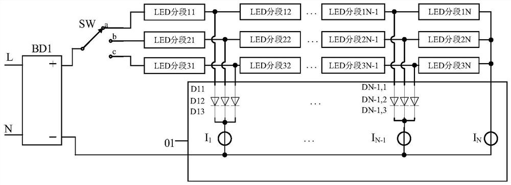
[0034] This embodiment provides a multi-group LED switching circuit, powered by the rectifier circuit BD1, including: three groups of LED unit groups, the first LED unit group includes LED segment 11, LED segment 12...LED segment 1N, the second LED unit group The second LED unit group includes LED segment 21 , LED segment 22 . . . LED segment 2N, and the third LED unit group includes LED segment 31 , LED segment 32 . . . LED segment 3N.

[0035] The distribution of the number of series LEDs in each segment only needs to meet the design requirements of the LED driver chip IC1 (the LED driver chips of various merchants have different requirements for the serial ratio of the LED segments used in order to meet the parameters of harmonics, surges, etc. recommended ratio).

[0036] The control circuit 01 is used to drive three LED unit groups, including: three linear current sources, which are set corresponding to the LED segments described in the N section, respectively: the first ...

Embodiment 2

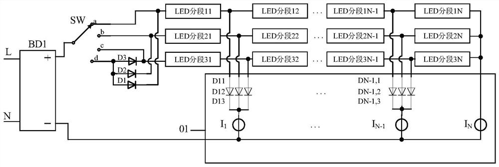
[0047] On the basis of Embodiment 1, this embodiment adds a lighting circuit for mixed-color light. Such as figure 2 As shown, on the basis of the schematic circuit diagram of Embodiment 1, the switch switching circuit SW also includes a hybrid contact d and several second diodes (this embodiment also uses three sets of LED unit groups as an example, so there are the first Two diodes D1, D2 and D3), the anodes of the second diodes D1, D2 and D3 are connected together and connected with the hybrid contact d, the cathodes of the second diodes D1, D2 and D3 are respectively connected with The anode connections of the first, second and third LED unit groups.

[0048] When the common end of the switch switching circuit SW is switched to be connected with the hybrid contact d, the first, second and third LED unit groups are connected to the power supply through the forward conducting second diodes D1, D2 and D3, and the LED The linear current sources I1, I2...IN of the drive chip...

Embodiment 3

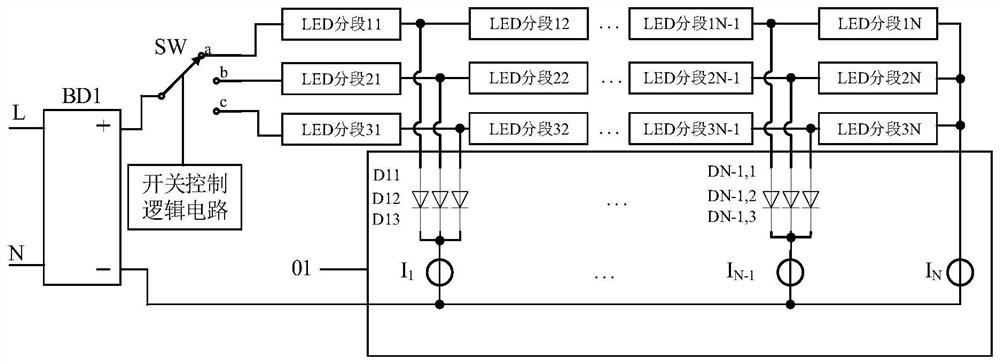
[0052] On the basis of Embodiment 1, this embodiment realizes the effect of mixed color light in different proportions. Such as image 3 As shown, on the basis of the circuit schematic diagram of Embodiment 1, the multi-group LED switching circuit also includes a switch control logic circuit for controlling the switching of the common terminal of the switch switching circuit; the switch control logic circuit includes a single or multiple output The signal generator is used for generating signals to control the switch conduction time of several LED unit groups.

[0053] Here, the switch switching circuit may include multiple common terminals, and the single or multiple signal generators in the switch control logic circuit output single or multiple signals for controlling each common terminal of the switch switching circuit according to different time ratios. Switching between different moving contacts, within a certain period of time, the signal controls the switch conduction ...


PUM


Abstract

The invention discloses a control circuit, a multi-group-LED switching circuit and an LED driving chip. The multi-group-LED switching circuit comprise a control circuit, M LED unit groups and a switchswitching circuit; each LED unit group comprises N LED subsections, namely a first LED subsection,..., an (N-1)th LED subsection and an Nth LED subsection which are sequentially connected in series;the head end of each LED unit group is the positive polarity end of the first LED subsection, and the tail end of each LED unit group is the negative polarity end of the Nth LED subsection; an AC signal serving as an input is arranged between one end of the switch switching circuit and a first end, and the other end of the switch switching circuit can be selectively connected to the head end of one of the M LED unit groups. According to the control circuit, the multi-group-LED switching circuit and the LED driving chip of the invention, the plurality of LED unit groups share one driving circuit through the switch switching circuit, so that the space is saved, wiring is easy, and the cost is saved; and diodes connected in series between LEDs and a linear current source block a discharge loop, so that the thorough switching of a plurality of groups of LEDs is realized.

Description

[0001] This application claims the priority of the Chinese patent application CN201910832321.0 with the filing date of September 4, 2019. technical field [0002] The invention belongs to the field of LED (light emitting diode) lighting, and in particular relates to a control circuit, a plurality of groups of LED switching circuits and an LED driving chip. Background technique [0003] In LED lighting products, the multi-segment linear constant current drive scheme is widely used. Usually, on the LED lighting equipment driven by linear constant current, the components of the linear constant current drive circuit and the grouped LED particles are welded on the aluminum plate. Only a separate drive circuit can be realized, which takes up a lot of space on the aluminum plate and greatly increases the difficulty of wiring, which in turn will increase the cost of the circuit. Contents of the invention [0004] The technical problem to be solved by the present invention is to p...

Claims


Application Information

Patent Timeline
Patent Type & Authority Applications(China)
IPC IPC(8): H05B45/30H05B45/20
Inventor 邵蕴奇
Owner SHANGHAI LOOALL ELECTRONICS CO LTD
Why Eureka
Try Eureka