Laser welding method and device for laser welding

A laser welding and laser beam technology, applied in laser welding equipment, welding equipment, metal processing equipment, etc., can solve the problems of beam energy loss, inability to change the focal length, increase the temperature of the shaping diffractive optical element, etc., to achieve small energy loss, Avoid bad soldering effects

Inactive Publication Date: 2021-03-26
BRANSON ULTRASONICS SHANGHAI
View PDF4 Cites 2 Cited by
  • Summary
  • Abstract
  • Description
  • Claims
  • Application Information

AI Technical Summary

Problems solved by technology

Although the shaped diffractive optical element can redistribute the energy of the laser beam, the refraction, reflection and transmission will occur when the laser passes through the shaped diffractive optical element, resulting in the loss of beam energy and increasing the temperature of the shaped diffractive optical element; at the same time, due to Diffraction phenomenon belongs to spatial distribution, so different spatial positions will form diffraction

Method used


Image

  • Laser welding method and device for laser welding
  • Laser welding method and device for laser welding
  • Laser welding method and device for laser welding

Examples


Embodiment Construction

[0049]Preferred embodiments of the present invention will now be described in detail with reference to the accompanying drawings. The following description is merely exemplary in nature and is not intended to limit the invention and its application or uses. In the various views, corresponding components or parts are provided with the same reference signs.

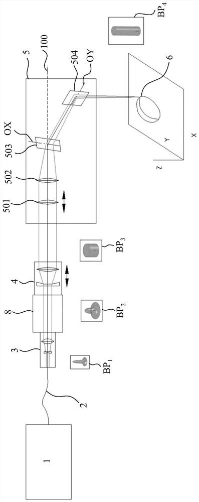
[0050] In the present invention, in order to better describe the characteristics of the laser beam, different spot shapes are used to represent some features of the laser beam, wherein the spot shape is a three-dimensional configuration, and the bottom surface shape of the three-dimensional configuration represents the cross-sectional shape of the laser beam, The height of each point in the shape of the bottom surface of the three-dimensional configuration represents the beam intensity or energy value of each point in the cross-sectional shape of the laser beam.

[0051] In this article, the term "optical path" refers to t...


PUM


Abstract

The invention relates to a laser welding method. The method comprises the following steps: generating laser beams with energy in Gaussian distribution; enabling the generated laser beams to form parallel beams through optical transformation, wherein the energy of the parallel beams is in Gaussian distribution; shaping the parallel beams with energy in Gaussian distribution into parallel beams withenergy in uniform distribution; and focusing the parallel beams with energy in uniform distribution to a welding part. The invention also relates to a device for laser welding using the method. Withthe method and the device, the welding defects caused by uneven heating can be reduced, and meanwhile, the device for laser welding is simplified, so that welding is carried out under the condition that the relative position between the device and a welding piece is not changed.

Description

technical field [0001] The present invention relates to the field of laser welding, and more specifically, to a laser welding method and a device for laser welding. Background technique [0002] This section provides background information related to the present disclosure which does not necessarily constitute prior art. [0003] Laser welding has been used in the welding of metals and plastics. It uses the characteristics of high laser energy and low attenuation during propagation, focuses the laser on the welding part of the welded part, uses laser energy to heat and melt the welding part, and The melted welded parts are pressed and held until they cool and are welded together. [0004] However, the laser beam emitted by most lasers is a Gaussian beam, that is, the energy distribution of its cross section obeys a Gaussian function. Therefore, the energy density at the center of the spot is much higher than that at the edge of the spot, resulting in a much higher temperatu...

Claims


Application Information

Patent Timeline
IPC IPC(8): B23K26/064B23K26/21B23K26/70
CPCB23K26/21B23K26/064B23K26/702
Inventor 冯学明
Owner BRANSON ULTRASONICS SHANGHAI
Why Eureka
Try Eureka