[0026] The present invention will be described in detail in connection with the accompanying drawings and specific examples, in order to better understand the invention and specific examples.
[0027] The preparation and sealing method for the preparation and sealing rock specimens for multi-field coupling triaxial tests, including the following steps:
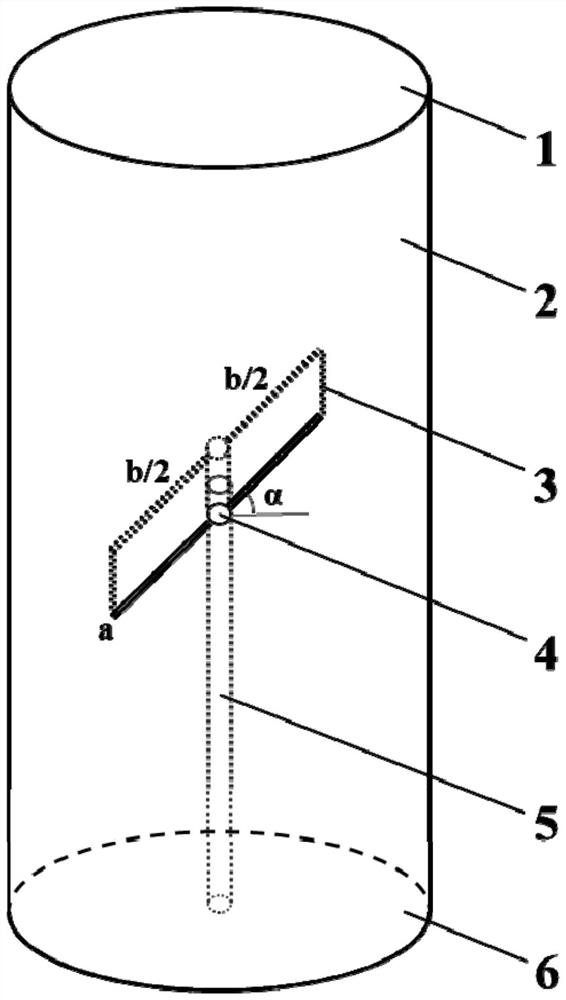
[0028] Step 1, complete rock sample preparation: Processing natural rock into standard cylindrical samples, figure 1 As shown, the unevenness error error between the inlet end surface 6 and the water end surface 1 is not more than 0.05 mm, and the inlet end surface 6 and the outlet end surface 1 perpendicular to the test piece axis, the maximum deviation is not more than 0.25 °. The standard cylindrical specimen has a diameter of 50 mm and a height of 100 mm.
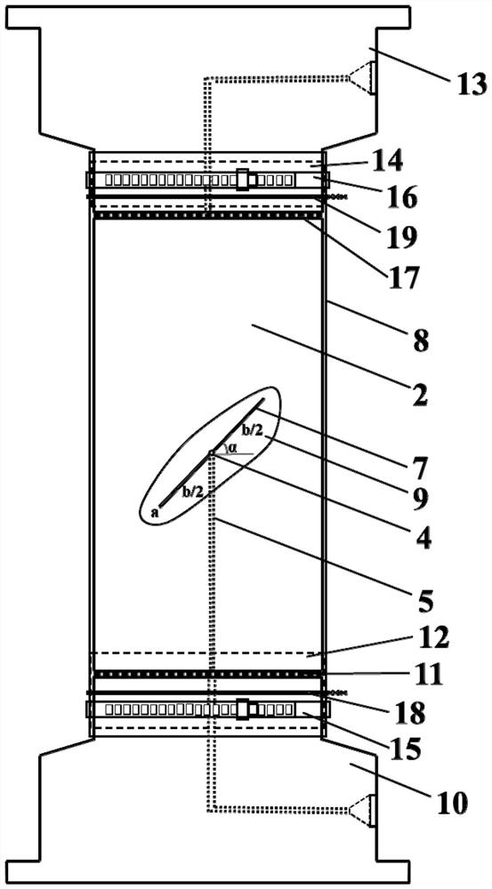
[0029] Step 2, rock sample crack processing: The standard cylindrical rock sample 2 prepared in step 1 is processed on the processing crack 3, figure 1 Indicated.
[0030] Firstly, water jet is used in the middle of the rock sample 2, and the length of the radial through hole 4 is the same as the diameter of the rock sample 2, and the diameter of the radial via 4 is 1 mm. The radial through hole 4 is used as a starting position of the crack 3 for the subsequent line.
[0031] Subsequently, the axial half-through hole 5 is vertically processed in the center of the rock sample 2 inlet end surface 6 until the length of the medium radial through hole 4 is connected, and the length is equal to one-half of the rock sample 2, axial direction. The half through hole 5 has a diameter of 1 mm, and the axial semi-through hole 5 serves as a permeate passage that allows the osmotic hydraulic pressure to the crack 3.
[0032] The cutting wire is passed through the central radial through hole 4, and the preform of the tilt α, length B and the width A is processed by wire cutting techniques. The prefabricated crack 3 extends toward both sides in a radial through hole 4, and its length B, the width A and the inclination angle α are variables, that is, the different rock samples are different, the preform width A is controlled by cutting wire specification, according to the cutting steel wire specification Test requirements for design. The present embodiment is selected: the prefabricated crack width A is 0.5 mm, and the inclination angle α is 45 °, and the length B is 2 cm.
[0033] The radial through hole 4, the axial half-through hole 5 and the prefabricated crack 3 should be processed in turn to avoid water jet to cause other damage to the rock sample, improve the processing rate of the split rock sample.
[0034] Step 3, the slit satin-containing water treatment: After measuring the size and quality of the split rock, the crack sample is completely immersed in deionized water, and the container is evacuated until no gas is esually, but the extraction time is not Level for less than 4 hours, and the vacuum pumping is complete 24 hours, so that the rock is completely saturated, and the non-saturated rock sample in the three-axis test continues to affect the penetration rate.
[0035] Step 4, the sewing rock is sealed: take out the saturated rock sample and remove the surface moisture, weigh the rock sample saturation, use figure 2 The method shown is sealed.
[0036] First, a small amount of quick dry cement slurry 7 is applied to the surface of the rock sample 2, and the crack is filld. After the cement slurry 7 is solidified, it has a proper intensity to prevent the heat shrink tube 8 from being caught in a prefabricated crack under higher pressure. rupture. The solidified excess cement slurry was placed flat, and the quick dry cement slurry was mixed with water in a ratio of 1: 1.
[0037] A layer of waterproof silica gel 9 is then applied to the surface of the prefabricated crack and to be hardened to prevent the penetration pressure liquid in the crack during the test.
[0038] After the rock sample is sealed, the pulverized rock sample 2 is placed on the seepage lower presser 10, and the first filtraminal film 11 should be placed between the cracked rock sample 2 and the seepage underflow head 10, avoiding the destruction of rock samples. The cutting filters entered the seepaged head clogging seepage pipe under penetration, and the first self-viscous 12 is wound into the contact position of the rock sample 2 and the seepage underflow head 10, and the first self-adhesive 12 is a rubber or tape.
[0039] The side surface of the seepage upper press 13 and the rock sample 2 contact end is also wound by the second self-viscous glue 14, and the sealing effect of the subsequent sealing hoop and the wire, the second self-adhesive 14 is a rubber or tape.
[0040]In the rock sample 2, the heat shrink tube 8 is extracted, the first sealing hoop 15 and the second sealing hoop 16, and the upper end surface of the rock sample 2 is sequentially placed in the upper end surface of the second filter film 17 and the shadrogenes. 13, heat shrinking The end of the tube 8 exceeds 1.5 cm of the rock sample 2, providing mounting space for wire and sealing hoop, and wrap the seepage head and rock sample 2 into a whole, and the heat shrink tube 8 uses a transparent heat shrinkable tube, which is convenient for the test. Take a photo of the rock sample destruction, and the highest operating temperature of the heat shrink tube 8 is not lower than the test temperature.
[0041] The heat shrink tube 8 is then heated by a thermal fan, which is contracted and closely fitted with the rock sample 2.
[0042] Finally, the first wire 18 and the first sealing hoop 15 are used in the seepage lower press 10 from the adhesive position, and the second wire 19 and the second sealing hoop are used at the bleedd head 13 since the adhesive position. 16 Double seals composed of double seals, wires and sealing hoops, the wire is close to the rock sample, and the sealing hoop is close to the seepage head side.
[0043] The above embodiments do not constitute a defined of the scope of the present invention, any modifications, equivalents, and improvements in the spirit and principles of the above embodiments, should be included within the scope of the invention.