Antenna common-caliber miniaturized microwave laser composite detection radar

A compound detection and microwave radar technology, applied in the field of measurement and testing, can solve unsolved problems such as synchronous detection, achieve the effect of reducing volume and weight, and efficient reception

Active Publication Date: 2021-03-26
BEIJING RES INST OF TELEMETRY +1
View PDF4 Cites 2 Cited by
  • Summary
  • Abstract
  • Description
  • Claims
  • Application Information

AI Technical Summary

Problems solved by technology

From October 2016 to March 2018, the ground-based LACROS system in Cyprus conducted cloud, aerosol and precipitation experiments for 18 months using a variety of remote sensing equipment, the main advanced remote sensing equipment including an aerosol LiDAR, a millimeter-wave cloud radar for mixed phase and ice cloud profile measurement and ice water content measurement; China Meteorological Administration is organizing a super-large city test project, in which the cloud observation mainly uses the same test site ground millimeter Boyun radar and lidar conduct collaborative remote sensing observations; the microwave laser collaborative detection schemes adopted in the above projects all adopt the same-site collaborative observation design of microwave radar and lidar, which does not solve the problem of simultaneous high-temporal and spatial simultaneous detection of the same cloud cluster at the same time and in the same direction

Method used


Image

  • Antenna common-caliber miniaturized microwave laser composite detection radar
  • Antenna common-caliber miniaturized microwave laser composite detection radar
  • Antenna common-caliber miniaturized microwave laser composite detection radar

Examples


Embodiment 1

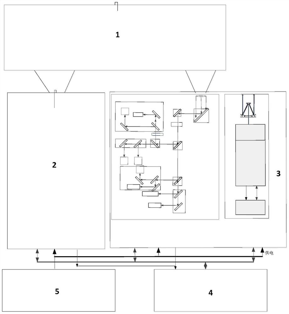
[0062] like Figure 1-2 As shown, a miniaturized microwave laser composite detection radar with a common aperture of the antenna includes a microwave laser common aperture antenna subsystem 1, a microwave radar subsystem 2 and a laser radar subsystem 3 connected to the microwave laser common aperture antenna subsystem 1, A system management and signal processing subsystem 4 and a power supply system 5 electrically connected to the microwave radar subsystem 2 and the laser radar subsystem 3;

[0063] The microwave laser co-aperture antenna subsystem 1 is used for transmitting laser signals and receiving laser echo signals, for transmitting microwave signals and receiving microwave echo signals, and for separating and collimating the laser echo signals and microwave echo signals;

[0064] The microwave radar subsystem 2 is used to receive the intermediate frequency microwave baseband signal output by the system management and signal processing subsystem 4 and amplify it into a m...

Embodiment 2

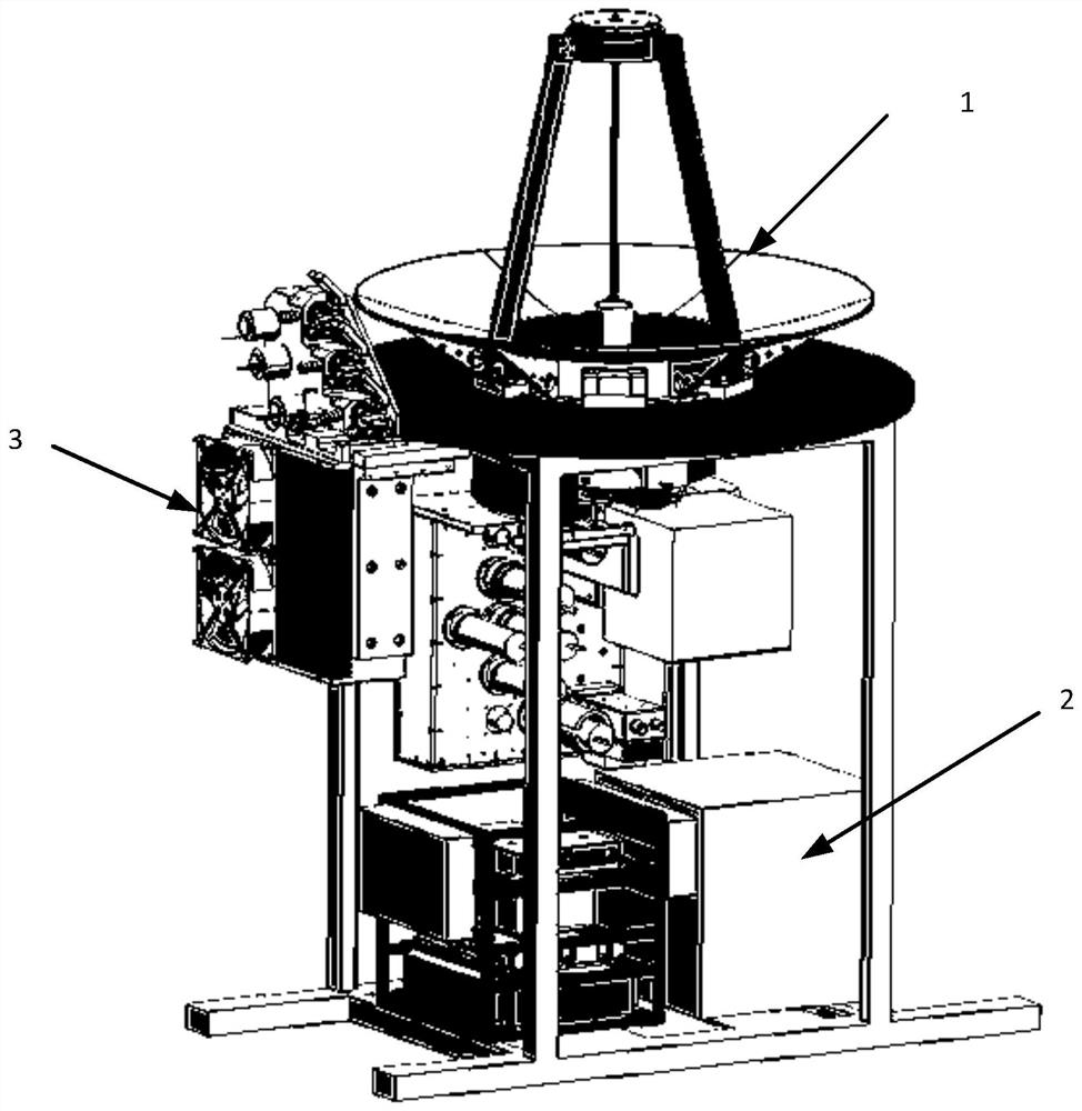
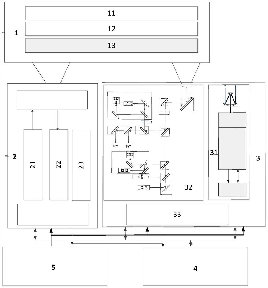
[0069] like Figure 3-4 As shown, a miniaturized microwave laser composite detection radar with a common aperture of the antenna includes a microwave laser common aperture antenna subsystem 1, a microwave radar subsystem 2 and a laser radar subsystem 3 connected to the microwave laser common aperture antenna subsystem 1, A system management and signal processing subsystem 4 and a power supply system 5 electrically connected to the microwave radar subsystem 2 and the laser radar subsystem 3;

[0070] The microwave laser co-aperture antenna subsystem 1 is used for receiving laser echo signals, for transmitting microwave signals and receiving microwave echo signals, and for separating and collimating laser echo signals and microwave echo signals;

[0071] The microwave laser common-aperture antenna subsystem 1 includes a microwave laser common-aperture antenna 11, and the microwave laser common-aperture antenna 11 is used to receive microwave echo signals and laser echo signals; ...

Embodiment 3

[0085] like Figure 3-4 As shown, a miniaturized microwave laser composite detection radar with a common aperture of the antenna includes a microwave laser common aperture antenna subsystem 1, a microwave radar subsystem 2 and a laser radar subsystem 3 connected to the microwave laser common aperture antenna subsystem 1, A system management and signal processing subsystem 4 and a power supply system 5 electrically connected to the microwave radar subsystem 2 and the laser radar subsystem 3;

[0086] The microwave laser co-aperture antenna subsystem 1 is used for receiving laser echo signals, for transmitting microwave signals and receiving microwave echo signals, and for separating and collimating laser echo signals and microwave echo signals;

[0087] The microwave laser common-aperture antenna subsystem 1 includes a microwave laser common-aperture antenna 11, and the microwave laser common-aperture antenna 11 is used to receive microwave echo signals and laser echo signals; ...


PUM


Abstract

The invention provides an antenna common-caliber miniaturized microwave laser composite detection radar, which comprises a microwave laser common-caliber antenna subsystem, a microwave radar subsystem, a laser radar subsystem and a system management and signal processing subsystem; software and hardware compounding and joint inversion are carried out through a W-band all-solid-state frequency modulation continuous wave cloud radar and a multi-wavelength Raman polarization laser radar to realize remote sensing detection of cloud and aerosol fine structures, echo signals of laser and microwavesbackscattered by the cloud and aerosol are received by a microwave and laser composite detection radar common-caliber antenna, and microwave echo and laser echo are separated through a space separation technology; detection processing of microwave echo signals and laser echo signals is achieved through a microwave detection channel and an optical detection channel respectively; and through microwave radar and laser radar system control and data inversion software running in a display and control computer, the functions of microwave laser composite radar control, state monitoring, echo signal and data processing and product display are achieved.

Description

technical field [0001] The invention relates to the technical field of measurement and testing, in particular to a miniaturized microwave laser composite detection radar with a common aperture. Background technique [0002] Atmospheric clouds and aerosols play an important role in global climate and environmental changes. Accurate cloud and aerosol information can deepen people's understanding of the earth's energy balance and improve the accuracy of numerical weather forecasting, which is of great significance to climate research. At the same time, a detailed understanding of the spatial distribution of aerosol characteristics is also a prerequisite for understanding the pollution mechanism and controlling pollution. [0003] Cloud and aerosol remote sensing detection technologies mainly include passive detection technologies such as imaging spectrometers, lidar technology and microwave radar technology. Compared with passive remote sensing detection technology, lidar and...

Claims


Application Information

Patent Timeline
Patent Type & Authority Applications(China)
IPC IPC(8): G01S13/86G01S17/87G01S7/02G01S7/41G01S7/48G01S7/481
CPCG01S13/865G01S17/87G01S7/02G01S7/41G01S7/481G01S7/4802
Inventor 赵一鸣何晓晶孙立刚魏祥通江柏森张凤梅于勇李凉海
Owner BEIJING RES INST OF TELEMETRY
Why Eureka
Try Eureka