Catadioptric eyepiece optical system and head-mounted display device
An optical system, catadioptric technology, applied in the optical field, to achieve the effect of light weight, easy processing and assembly, and large field of view
- Summary
- Abstract
- Description
- Claims
- Application Information
AI Technical Summary
Problems solved by technology
Method used
Image

Examples
Embodiment 1
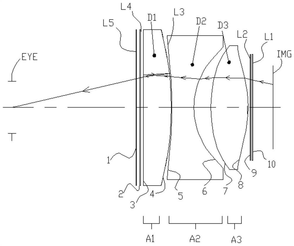
[0102] attached figure 1 It is a 2D structural diagram of the eyepiece optical system of the first embodiment, including an optical polarizer L5, a first phase retarder L4, a first lens group A1, The second lens group A2, the third lens group A3, the second phase retarder L4, and the linear polarizer L5; wherein, the optical polarizer L5 can selectively project the linearly polarized light p light and reflect the linearly polarized light s light; or, can Selectively project linearly polarized light s and reflect linearly polarized light p; a semi-transparent and semi-reflective optical surface L3 is included between the first lens group A1, the second lens group A2 and the third lens group A3. The first lens group A1 in the optical system is composed of the first lens D1, the first lens D1 is a plano-convex lens; the second lens group A2 is composed of the second lens D2, the second lens D2 is a biconcave lens, and the third lens group A3 is composed of Composed of the third ...
Embodiment 2
[0108] attached Figure 5 It is a 2D structural diagram of the eyepiece optical system of the second embodiment, including an optical polarizer L5, a first phase retarder L4, a first lens group A1, The second lens group A2, the third lens group A3, the second phase retarder L4, and the linear polarizer L5; wherein, the optical polarizer L5 can selectively project the linearly polarized light p light and reflect the linearly polarized light s light; or, can Selectively project linearly polarized light s and reflect linearly polarized light p; a semi-transparent and semi-reflective optical surface L3 is included between the first lens group A1, the second lens group A2 and the third lens group A3. The first lens group A1 in the optical system is composed of the first lens D1, and the first lens D1 is a plano-convex lens; the second lens group A2 is composed of the second lens D2, and the second lens D2 is a biconcave lens; the third lens group A3 is composed of Composed of the ...
Embodiment 3
[0114] attached Figure 9 It is a 2D structural diagram of the eyepiece optical system of the third embodiment, including an optical polarizer L5, a first phase retarder L4, a first lens group A1, The second lens group A2, the third lens group A3, the second phase retarder L4, and the linear polarizer L5; wherein, the optical polarizer L5 can selectively project the linearly polarized light p light and reflect the linearly polarized light s light; or, can Selectively project linearly polarized light s and reflect linearly polarized light p; a semi-transparent and semi-reflective optical surface L3 is included between the first lens group A1, the second lens group A2 and the third lens group A3. The first lens group A1 in the optical system is composed of the first lens D1, and the first lens D1 is a plano-convex lens; the second lens group A2 is composed of the second lens D2, and the second lens D2 is a biconcave lens; the third lens group A3 is composed of The third lens D3...
PUM
 Abstract
Description
Claims
Application Information
 - R&D
- Intellectual Property
- Life Sciences
- Materials
- Tech Scout
- Unparalleled Data Quality
- Higher Quality Content
- 60% Fewer Hallucinations
Browse by: Latest US Patents, China's latest patents, Technical Efficacy Thesaurus, Application Domain, Technology Topic, Popular Technical Reports.
© 2025 PatSnap. All rights reserved.Legal|Privacy policy|Modern Slavery Act Transparency Statement|Sitemap|About US| Contact US: help@patsnap.com