Eureka AIR delivers breakthrough ideas for toughest innovation challenges, trusted by R&D personnel around the world.

Centrifugal filter

A centrifugal and filter technology, applied in the field of filters, can solve the problems of difficult-to-filter cloth forming filter cake, suitable filter type centrifuges, self-weight and other problems, and achieve the effect of improving filtration efficiency

Inactive Publication Date: 2003-10-29
沈庞录
View PDF0 Cites 0 Cited by
  • Summary
  • Abstract
  • Description
  • Claims
  • Application Information

AI Technical Summary

Problems solved by technology

These two types of solid-liquid separation machinery have many defects when separating high-flow, thin suspensions containing particles or fine fibers: filter centrifuges are only suitable for suspensions with solid phase concentrations ≥ 30%; sedimentation centrifuges are generally It is only suitable for working conditions where the solid phase concentration is > 2%, and the solid-liquid phase density difference is ≥ 0.1g / cm
There are also filter machines with a large flow rate, which are mainly rotary drum filters. However, if the solid phase is too heavy or too small, and the solid phase sedimentation speed is too fast or too slow, it will be difficult to form a filter cake on the filter cloth, thus restricted in use
In addition, most of these filters also need vacuum, stirring
Pressurization, pre-coating and other supporting facilities, the device has a large volume and heavy weight

Method used


Image

  • Centrifugal filter
  • Centrifugal filter
  • Centrifugal filter

Examples


Embodiment Construction

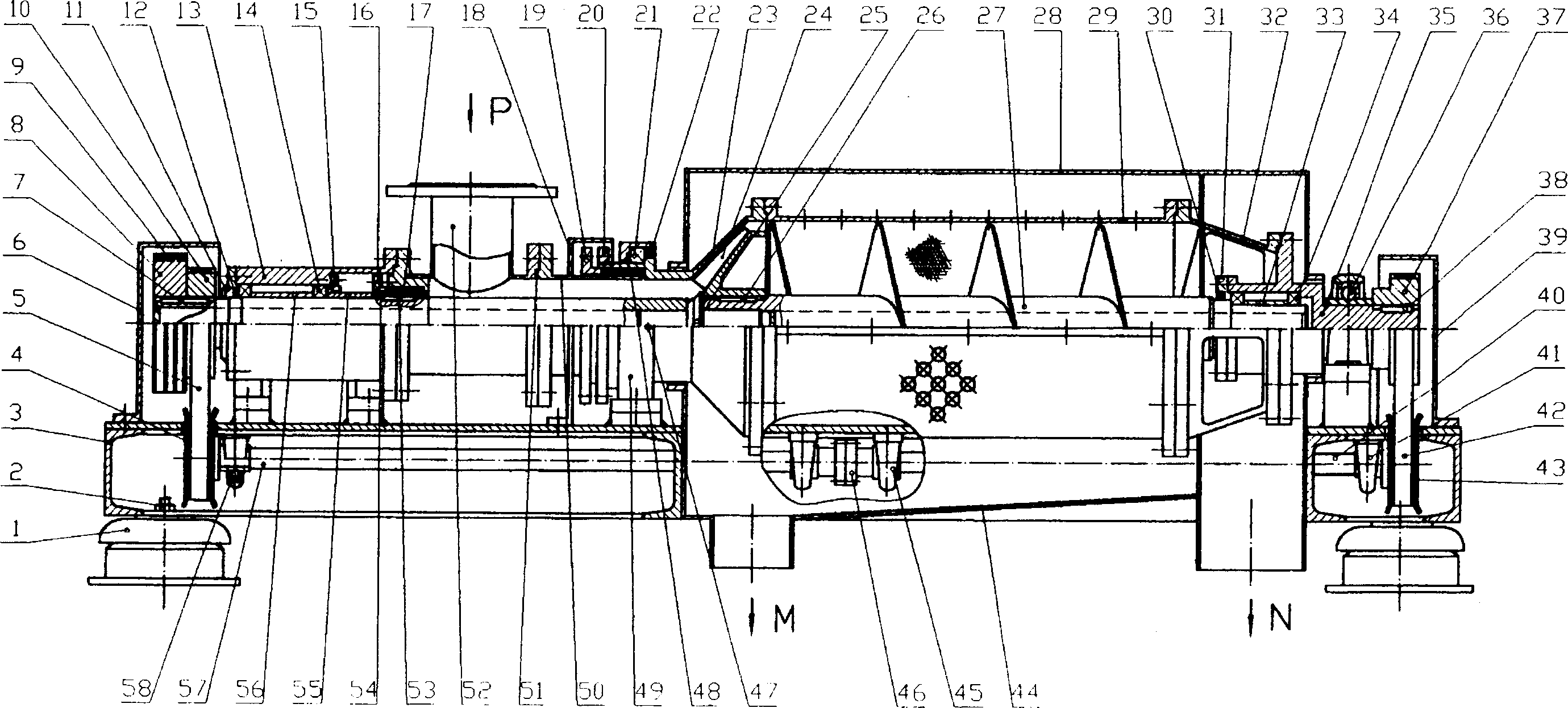
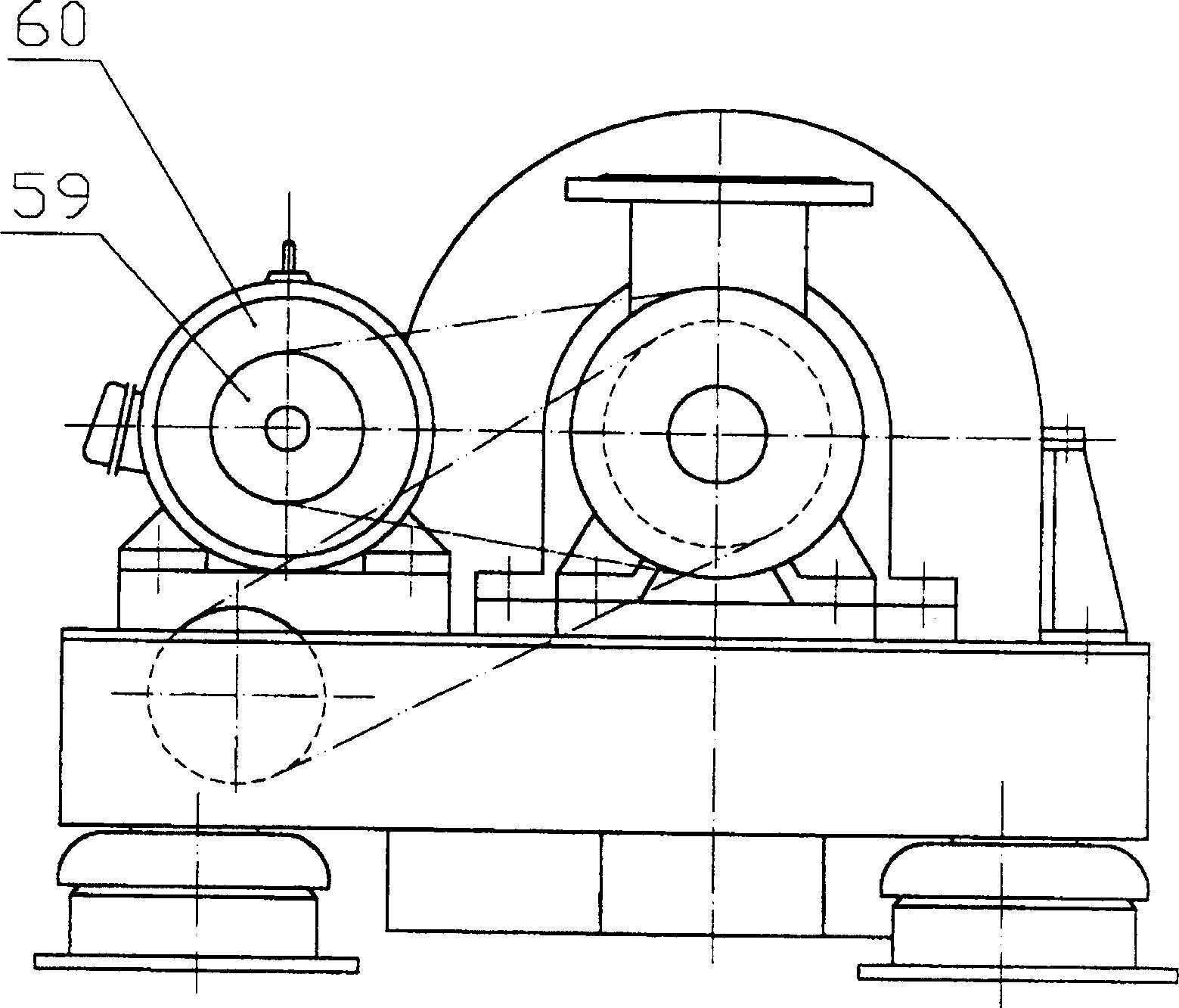
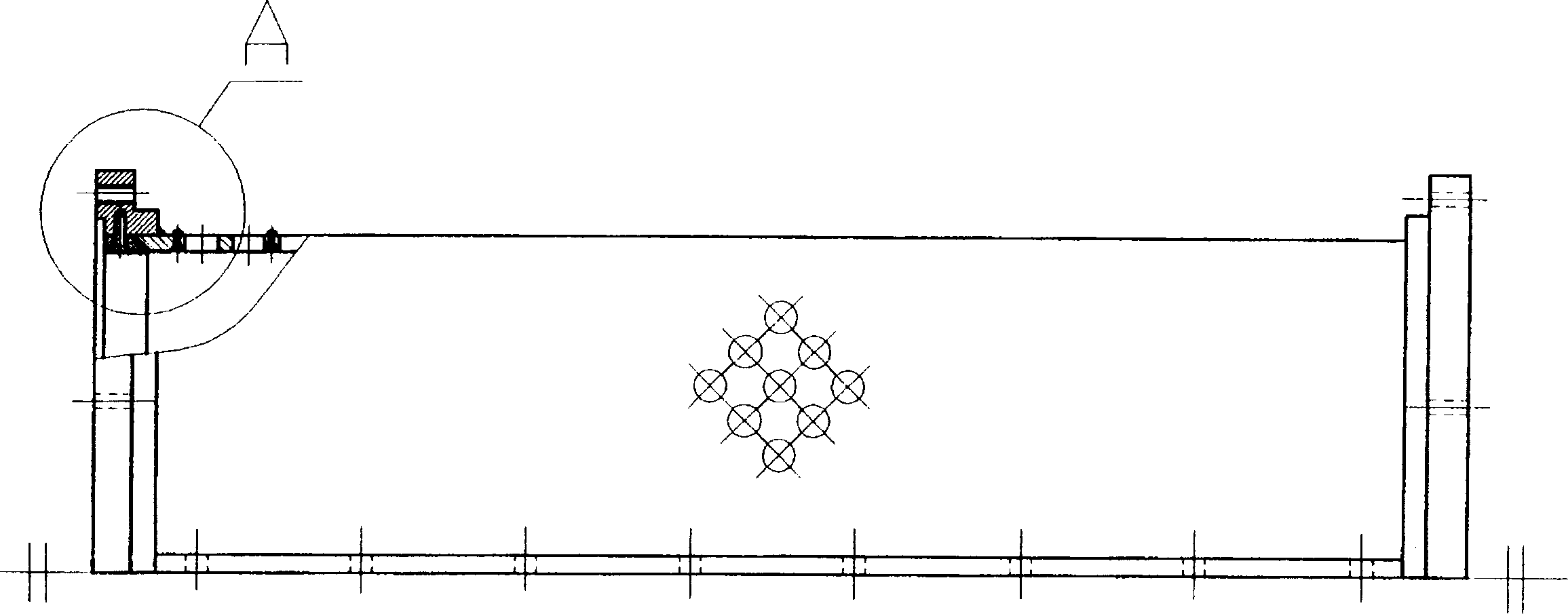
[0029] refer to figure 1 , figure 2 , the present invention includes a base 3 and various shells and supporting bases fixedly connected with the base 3 . Described housing can be divided into upper machine cover 28, lower machine cover 44, and cover shell 6 and cover shell 18, and described support seat can be divided into front bearing seat 13, middle bearing seat 49, belt seat bearing 36, front belt Seat bearing 58, middle band seat bearing 45, rear band seat bearing 41.

[0030] Put a screw shaft 27 in upper and lower machine cover 28,44, this screw shaft 27 maximum diameter φ 121 (small φ 61 of inner hole diameter), has screw blade on the screw shaft 27. One end of screw shaft 27 is connected with front axle 25, and this front axle 25 is connected with base 3 by two bearings 14, front bearing block 13, and the other end is rotationally connected with rear axle 35 by two bearings 34, and is connected by belt seat Bearing 36 supports. The front end of the front axle 25 ...


PUM


Abstract

A centrifugal filter, including a base and a housing, etc., one end of a screw shaft with a helical blade is connected to the base through a front shaft and a bearing seat, and the other end is rotationally connected to a rear shaft; the rotary screen is set outside the screw shaft, and one end It is connected to the base, and the other end is connected to the rear axle. One end of the front axle is equipped with a timing pulley. The front drive shaft and the rear drive shaft are respectively connected to the bottom of the base through the front bearing with seat, the middle bearing with seat and the rear bearing with seat. The front and rear transmission shafts are connected by a coupling, and one end of the front transmission shaft is provided with a transmission pulley, one end of the rear transmission shaft is provided with a timing belt pulley, and one end of the rear transmission shaft is also provided with a timing belt pulley. The invention can handle large flow and suspensions containing particles or fine fibers. The impeller cooperates with the rotary sieve to make the suspension generate filtration pressure in the rotary sieve, which improves the filtration efficiency. The screw shaft can automatically and continuously separate the solid and liquid phases. The invention is suitable for solid-liquid separation and recovery of solid-phase substances in industrial waste liquids such as chemical industry, textile, food, medicine and metallurgy.

Description

technical field [0001] The invention relates to a filter, in particular to a centrifugal filter capable of separating solid and liquid. It uses a built-in centrifugal pump, a screw shaft with screw blades and a rotary screen set outside the screw shaft, and can handle thin suspensions with large flows and containing particles or fine fibers. Background technique [0002] The solid-liquid separation machinery in the prior art is divided into two major categories of centrifugal machinery and filtering machinery. These two types of solid-liquid separation machinery have many defects when separating high-flow, thin suspensions containing particles or fine fibers: filter centrifuges are only suitable for suspensions with solid phase concentrations ≥ 30%; sedimentation centrifuges are generally It is only suitable for working conditions where the solid phase concentration is > 2%, and the solid-liquid phase density difference is ≥ 0.1g / cm. This type of mechanical structure is...

Claims


Application Information

Patent Timeline
IPC IPC(8): B04B1/00B04B3/04B04B7/16B04B11/08
Inventor 沈庞录
Owner 沈庞录
Why Eureka
Eureka Blog
Learn More