

Automatic grouting assembly line for hand mold manufacturing and hand mold manufacturing method
A technology of automatic grouting and manufacturing method, applied in the field of assembly line, can solve the problems of inability to meet the requirements of production orders, the number of grouting times and the low work efficiency, so as to solve the limitation of the number of grouting times, reduce the production labor intensity, and improve the work efficiency. The effect of efficiency
- Summary
- Abstract
- Description
- Claims
- Application Information
AI Technical Summary
Problems solved by technology
Method used
Image

Examples
Embodiment 1
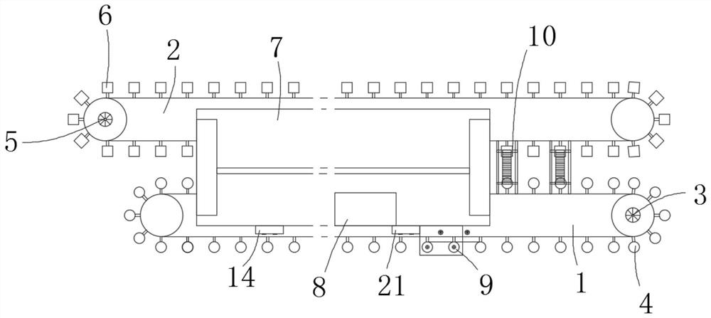
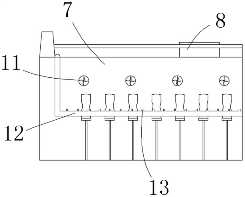
[0038] see Figure 1-Figure 11 , the present invention provides a technical solution: an automatic grouting line for hand mold making, including a first conveying line 1 and a second conveying line 2, and one end of the first conveying line 1 is provided with a circular wheel motor 3 for transmission, so A circular wheel 4 is fixedly arranged on the first conveying line 1, the circular wheel motor 3 is connected to the circular wheel 4 through a chain, and one end of the second conveying line 2 is provided with a square A wheel motor 5, a square wheel 6 is fixedly arranged on the second conveying line 2, the square wheel motor 5 is connected to the square wheel 6 through a chain, the first conveying line 1 and the The first drying chamber 7 is fixedly arranged between the second conveying lines 2, the top of the first drying chamber 7 is fixedly arranged with a mud storage box 8, and one side of the first drying chamber 7 is fixedly arranged with a A grout gun 9, the mud stor...
Embodiment 2
[0048] The manufacturing method of hand model, comprises the following steps:
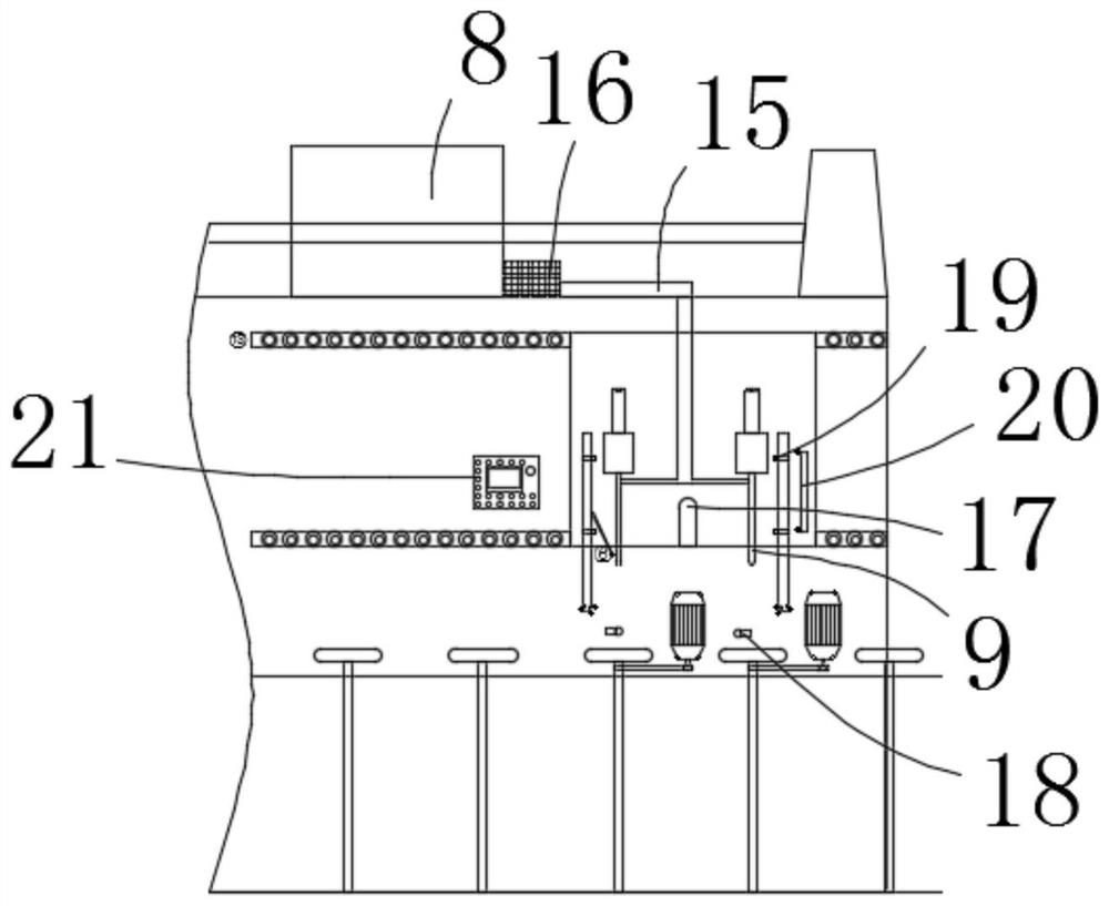
[0049]S1. From the mud tank through the diaphragm pump, the mud enters the mud storage tank 8 on the assembly line through the pipeline, and enters the grouting gun 9 through the 160-mesh filter screen 16 to prepare for grouting;
[0050] S2. When the model turns to the grouting area, through the black dot electronic eye photosensitive controller 18, when the model rotates to the position to be grouted, the black dot electronic eye photosensitive controller 18 senses the black spot on the model, and the circular wheel 4 stop spinning;
[0051] S3. Determine the descending and rising position height of the grouting gun 9 through the electronic eye photosensitive controller 28, control the position of the grouting gun 9 after entering the model through the electronic eye photosensitive controller 28, and provide the power of the grouting gun 9 rising and falling through the cylinder 17 , control the...
PUM
 Abstract
Description
Claims
Application Information