
Working method of dredging robot

A working method and robot technology, applied to mechanically driven excavators/dredgers, earth movers/shovels, construction, etc., can solve the problems of high cost, difficulty in collecting a single small-volume valve, and large space occupation, etc. problem, to achieve the effect of compact structure

Active Publication Date: 2021-03-30
CHANGSHA UNIVERSITY OF SCIENCE AND TECHNOLOGY
View PDF5 Cites 0 Cited by
  • Summary
  • Abstract
  • Description
  • Claims
  • Application Information

AI Technical Summary

Problems solved by technology

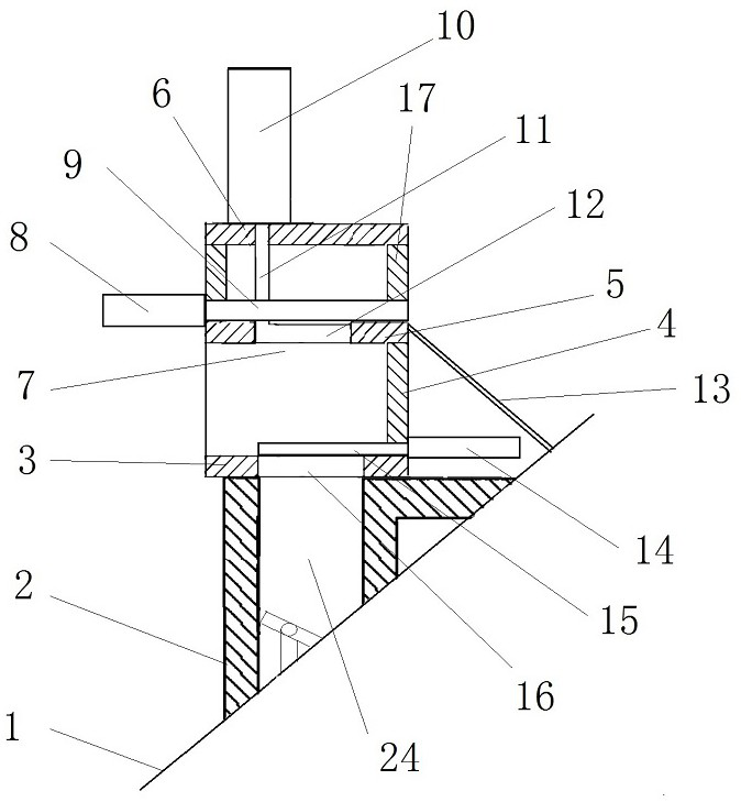
[0004] 1. The dredging equipment in the prior art transports the adsorbed sludge to the downstream treatment process through pipelines. However, the sludge pipeline needs to be controlled on and off, which requires valves to be installed on the sludge pipeline. However, for flexible pipes, The valve cannot be supported at all; the solution to this problem in the prior art is to set the valve inside the equipment casing, which makes the inside of the equipment casing more crowded, and when there is a need for replacement, maintenance, etc., it is inconvenient to disassemble and repair the valve
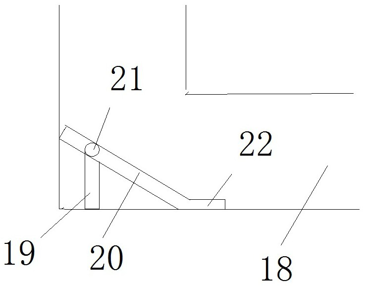
[0005] 2. In the dredging pipeline of the prior art, after the work is completed, there are dead angles in important parts such as valves, and the silt in the dead angle will accumulate and harden, blocking the pipeline
[0006] 3. The dredging technology under the existing technology includes technologies such as purging and cleaning. However, both purging and cleaning require additional media, such as the storage of cleaning fluid, which will take up a lot of space
[0007] 4. The dredging technology under the existing technology can only complete a single dredging, and the cost of circular dredging is relatively high and takes up a lot of space, such as the dredging assembly line
[0008] 5. The dredging pipelines in the prior art are often bent at right angles, and an inclined guide surface can be optionally provided, but standard molds cannot be used for the guide surface, which will increase the cost of processing molds
[0009] 6. For non-assembly lines, it is difficult for a single small-volume valve to collect after dredging, or there is nowhere to place the dredged sludge

Method used


Image

  • Working method of dredging robot
  • Working method of dredging robot
  • Working method of dredging robot

Examples


Embodiment Construction

[0051]As shown in the figure: a working method of a dredging robot, the dredging robot includes a dredging equipment housing, a control unit, a monitoring module, a communication module, a power system, a sewage system, and the power system comprises a machine body. Hydraulic stations, hydraulic valves, tubes, crawler motion systems, baffles, cylinders, hydraulic stations include power motor, fuel tank, oil pump; the power motor provides power for the oil pump, the oil pump to suck the oil in the fuel tank Out of the oil pipe, the hydraulic valve controls the oil passage of the tube, the oil pipe, supplies power oil to the track motion system, and the outer side of the track moving system is provided with the baffle, machine The load is set above the track motion system.

[0052]The working methods include: real-time monitoring methods, traveling dredging methods, stacking a sludge dredging method, cleaning method.

[0053]The real-time monitoring method includes a guardrail above the out...


PUM


Abstract

The invention discloses a working method of a dredging robot. The dredging robot comprises a dredging equipment shell, a control part, a monitoring module, a communication module, a power system and asewage discharging system. The power system comprises a machine body carrying plate, a hydraulic station, a hydraulic valve, an oil pipe, a crawler belt movement system, a baffle and an oil cylinder.A power motor, an oil tank and an oil pump are arranged in the hydraulic station. The power motor provides power for the oil pump, and the oil pump sucks out oil in the oil tank and supplies the oilinto the oil pipe. The working method comprises a real-time monitoring method, an advancing dredging method, an accumulated silt dredging method and a cleaning method.

Description

Technical field[0001]The present invention relates to the field of urban pipelines, and in particular to a working method of dredging robot.Background technique[0002]The current application field of dredging equipment is mainly distributed in Darfuched, circulating pool dredging, urban dark or dredging, large pipe dredging, urban river dredging, culvert, etc. The main difficulties are in this kind of dredging work. The operation environment is complex, and the divers cannot go deep into the bottom of the dark channel, and the manual survey and manual dredging will make the work efficiency discount. For the dredging equipment in the urban pipe network, due to the lack of maintenance of the municipal pipe network, it is easy to generate a 0.1 m-0.7 m thick silt, and many old pipelines in the urban area use rain-saving flow. The rain is large. When it is easy to cause clogging, so that the water in the city is serious. Therefore, the use of multi-functional integrated dredging equipmen...

Claims


Application Information

Patent Timeline
IPC IPC(8): E02F5/28E02F3/88E02F3/90E02F3/92E02F9/08
CPCE02F5/28E02F5/282E02F3/8866E02F3/90E02F3/92E02F3/9212E02F3/9237E02F3/9243E02F9/0891
Inventor 常留红李飘袁卓章付君李晨玉石豪杰郭洋毛聪
Owner CHANGSHA UNIVERSITY OF SCIENCE AND TECHNOLOGY
Learn More