
Photon-assisted pulse system microwave radar detection method and device

A technology of microwave radar and detection method, which is applied in measurement devices, radio wave measurement systems, reflection/re-radiation of radio waves, etc., can solve the problem of improving the detection distance of imaging radar, limiting processing speed, and improving the detection distance of microwave photonic imaging radar systems. and other problems to achieve the effect of improving the quality and improving the detection distance.

Pending Publication Date: 2021-03-30
NANJING UNIV OF AERONAUTICS & ASTRONAUTICS
View PDF0 Cites 4 Cited by
  • Summary
  • Abstract
  • Description
  • Claims
  • Application Information

AI Technical Summary

Problems solved by technology

However, most of the existing high-resolution microwave imaging radar research based on microwave photonics focuses on how to further improve the resolution, and there is no research on improving the detection range of microwave photon imaging radar systems, especially in long-distance situations.
[0004] With the improvement of the detection distance, microwave imaging radar, especially the imaging radar based on the de-skewing system, faces two problems: on the one hand, it is difficult to increase the signal power based on the FM continuous wave method, which cannot meet the needs of long-distance detection; The amount of oblique data is greatly increased, limiting the processing speed
The above problems limit the further improvement of imaging radar detection range

Method used


Image

  • Photon-assisted pulse system microwave radar detection method and device
  • Photon-assisted pulse system microwave radar detection method and device
  • Photon-assisted pulse system microwave radar detection method and device

Examples


Embodiment Construction

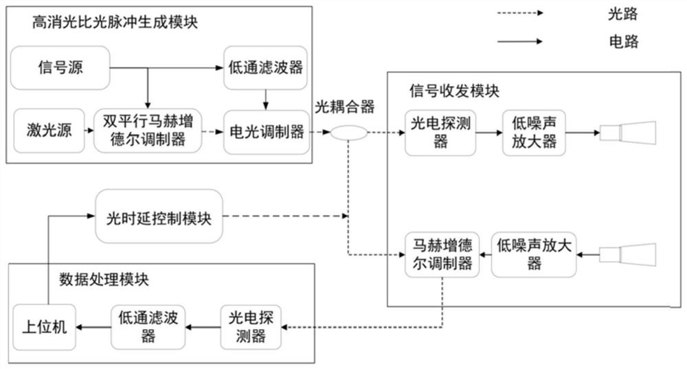
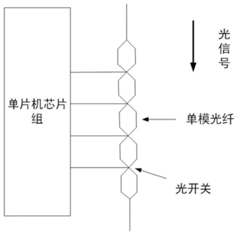
[0027] Aiming at the problem that the existing radar technology is difficult to meet the requirements of long distance and high precision at the same time, the solution idea of ​​the present invention is to improve the existing pulse system microwave radar based on microwave photon technology, and greatly improve the pulse detection signal through high extinction ratio processing in the optical domain The quality of the single pulse can be improved, and the detection distance of the single pulse can be improved; and the purpose of matching deskewing can be achieved through the delay matching of the optical signal, which can greatly reduce the data volume of the microwave imaging radar based on the deskewing system in the case of long distances, so as to meet the long-distance, The detection requirements of high-resolution imaging radar.

[0028] The photon-assisted pulse system microwave radar detection method proposed by the present invention is specifically as follows:

[00...


PUM


Abstract

The invention discloses a photon-assisted pulse system microwave radar detection method, and the method comprises the steps: carrying out the double-sideband modulation of carrier suppression of an optical carrier through a linear frequency modulation microwave pulse signal; performing minimum point modulation on the generated carrier-suppressed double-sideband modulation signal by using an envelope signal of the linear frequency modulation microwave pulse signal through an electro-optical modulator to generate a high extinction ratio optical pulse, dividing the high extinction ratio optical pulse into two paths, one path being used as an optical intrinsic reference signal, and the other path being used as an optical intrinsic reference signal; converting the other path into an electric pulse signal to be emitted as a radar detection signal; and carrying out optical domain mixing dechirping processing on the radar echo signal and the optical intrinsic reference signal subjected to timedelay matching to realize two-dimensional imaging of the target. The invention further discloses a photon-assisted pulse system microwave radar detection device. According to the invention, the detection requirements of long-distance and high-resolution imaging radar can be met.

Description

technical field [0001] The invention relates to the technical field of microwave radar, in particular to a photon-assisted pulse system microwave radar detection method and device. Background technique [0002] Microwave imaging radar, as a method that can meet the needs of all-weather and all-weather detection at this stage, is often used in areas such as autonomous driving, geological and terrain exploration, marine pollution detection, and disaster prevention and mitigation. At the same time, microwave imaging radar is also highly valued by various countries in the military, and can be used to achieve accurate and intelligent identification of targets. [0003] Range resolution is an important indicator of microwave imaging radar, which depends on the signal bandwidth of the radar system. However, the traditional method is limited by the "electronic bottleneck" and it is difficult to further expand the bandwidth. Due to its technical advantages such as large bandwidth, ...

Claims


Application Information

Patent Timeline
IPC IPC(8): G01S13/89G01S7/282G01S7/285
CPCG01S13/89G01S7/282G01S7/285
Inventor 王祥传刘思捷潘时龙张江涛张方正朱丹
Owner NANJING UNIV OF AERONAUTICS & ASTRONAUTICS
Learn More