
Semiconductor cleaning equipment

A technology for cleaning equipment and semiconductors, used in the manufacture of semiconductor/solid-state devices, cleaning methods using liquids, cleaning methods and utensils, etc. It can solve problems such as human danger, safety accidents, and environmental pollution, and reduce the probability of safety accidents. , The effect of improving the safety of use and reducing the probability of the leakage of the body

Active Publication Date: 2021-04-02
BEIJING NAURA MICROELECTRONICS EQUIP CO LTD
View PDF12 Cites 0 Cited by
  • Summary
  • Abstract
  • Description
  • Claims
  • Application Information

AI Technical Summary

Problems solved by technology

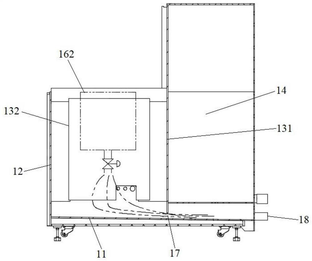
[0004] But, because water tank 162 is to wash the wafer after chemical cleaning, therefore, the water that water tank 162 discharges can contain the chemical liquid of low concentration, and chemical liquid Usually includes H2SO4, HCL, NH4OH, H2O2, HF and other corrosive and toxic chemical reagents, these chemical liquids wash the bottom plate 11 and side plate 12 for a long time, will cause corrosion to the welding joint between the bottom plate 11 and side plate 12, and cause water and low-concentration chemical liquids in the water to flow from the bottom plate 11 and the side plate 12 are leaking at the welding place, polluting the environment, causing danger to people, and leading to safety accidents

Method used


Image

  • Semiconductor cleaning equipment
  • Semiconductor cleaning equipment
  • Semiconductor cleaning equipment

Examples


Embodiment Construction

[0029] In order for those skilled in the art to better understand the technical solutions of the present invention, the semiconductor cleaning equipment provided by the present invention will be described in detail below in conjunction with the accompanying drawings.

[0030] Such as Figure 3-Figure 5 As shown, this embodiment provides a semiconductor cleaning device, including a body 20 and a chemical liquid tank 21, a water tank 22, a chemical liquid discharge pipe 23, a water discharge pipe 24, a cleaning liquid distribution assembly and a liquid detection component arranged in the main body 20 25, wherein, the chemical liquid tank 21 is used to chemically clean the wafer, and the water tank 22 is used to wash the chemically cleaned wafer, and the cleaning liquid distribution assembly is communicated with the chemical liquid tank 21 and the water tank 22 respectively, and is used to supply the chemical liquid tank 21 and the water tank 22 respectively. Chemical liquid and ...


PUM


Abstract

The invention provides semiconductor cleaning equipment. The semiconductor cleaning equipment comprises a body, and further comprises a chemical liquid tank, a water tank, a chemical liquid dischargepipe, a water discharge pipe, a cleaning liquid distribution assembly and a liquid detection part which are arranged in the body; the chemical liquid tank and the water tank are used for chemically cleaning and washing wafers correspondingly, and the cleaning liquid distribution assembly communicates with the chemical liquid tank and the water tank and is used for conveying chemical liquid and water to the chemical liquid tank and the water tank; one end of the chemical liquid discharge pipe communicates with the chemical liquid tank, and the other end of the chemical liquid discharge pipe penetrates through the body and extends out of the body to discharge the chemical liquid in the chemical liquid tank out of the body; one end of the water discharge pipe communicates with the water tank,and the other end of the water discharge pipe penetrates through the body and extends out of the body to discharge the water in the water tank out of the body; and the liquid detection part is used for detecting the liquid leaked into the body. According to the semiconductor cleaning equipment, the probability of liquid leakage of the body can be reduced, so that the probability of safety accidents is reduced, and the use safety is improved.

Description

technical field [0001] The present invention relates to the technical field of semiconductor equipment, in particular to semiconductor cleaning equipment. Background technique [0002] Semiconductor cleaning equipment is used to clean wafers to remove organic matter, natural oxide layer, particles, metal ions and other pollutants in the wafer. [0003] Such as figure 1 and figure 2 As shown, the body of the existing semiconductor cleaning equipment includes a base plate 11, a side plate 12, a first partition 131 and a second partition 132, and the side plate 12 surrounds the base plate 11 and is welded with the base plate 11 to form a cavity. The first partition 131 is arranged in the cavity, and the cavity is divided into a chemical liquid distribution system (Chemical Dispense System, referred to as CDS) chamber 14 and a cleaning chamber, and the second partition 132 is arranged in the cleaning chamber to separate the cleaning chamber. It is a chemical cleaning chamber...

Claims


Application Information

Patent Timeline
IPC IPC(8): B08B3/04B08B13/00G01M3/04G01N33/00H01L21/67
CPCB08B3/04B08B13/00H01L21/67057H01L21/67253G01M3/04G01N33/00
Inventor 刘东旭
Owner BEIJING NAURA MICROELECTRONICS EQUIP CO LTD
Learn More