A radially or angularly polarized laser device based on optical parametric chirped pulse amplification

An angularly polarized, chirped pulse technology, applied in lasers, laser parts, structure/shape of optical resonators, etc. and other problems, to achieve the effect of tunable wavelength and high pulse contrast.

Active Publication Date: 2022-03-08
SHANGHAI INST OF OPTICS & FINE MECHANICS CHINESE ACAD OF SCI
View PDF4 Cites 0 Cited by
  • Summary
  • Abstract
  • Description
  • Claims
  • Application Information

AI Technical Summary

Problems solved by technology

[0004] However, different spatial positions of radially or angularly polarized light have different polarization states. The traditional optical parametric chirped pulse amplification (OPCPA) laser system is limited by the requirements of the grating on the laser polarization and the phase matching requirements of the amplifying crystal. Inability to fully amplify radially or azimuthally polarized light, resulting in very poor quality output radially or azimuthally polarized laser light

Method used


Image

  • A radially or angularly polarized laser device based on optical parametric chirped pulse amplification
  • A radially or angularly polarized laser device based on optical parametric chirped pulse amplification
  • A radially or angularly polarized laser device based on optical parametric chirped pulse amplification

Examples


Embodiment Construction

[0024] In order to make the object, technical solution and advantages of the present invention more clear, the present invention will be further described in detail below in conjunction with the accompanying drawings and embodiments. It should be understood that the specific embodiments described here are only used to explain the present invention, not to limit the present invention.

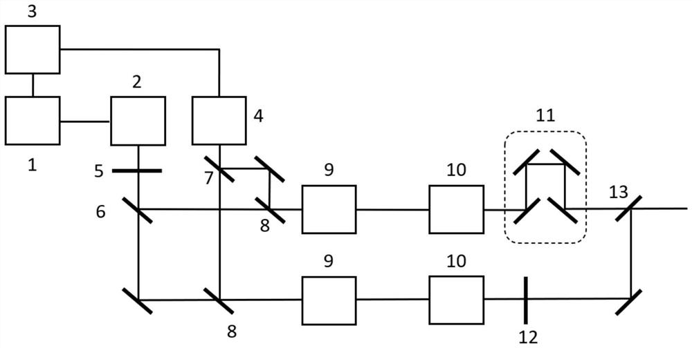
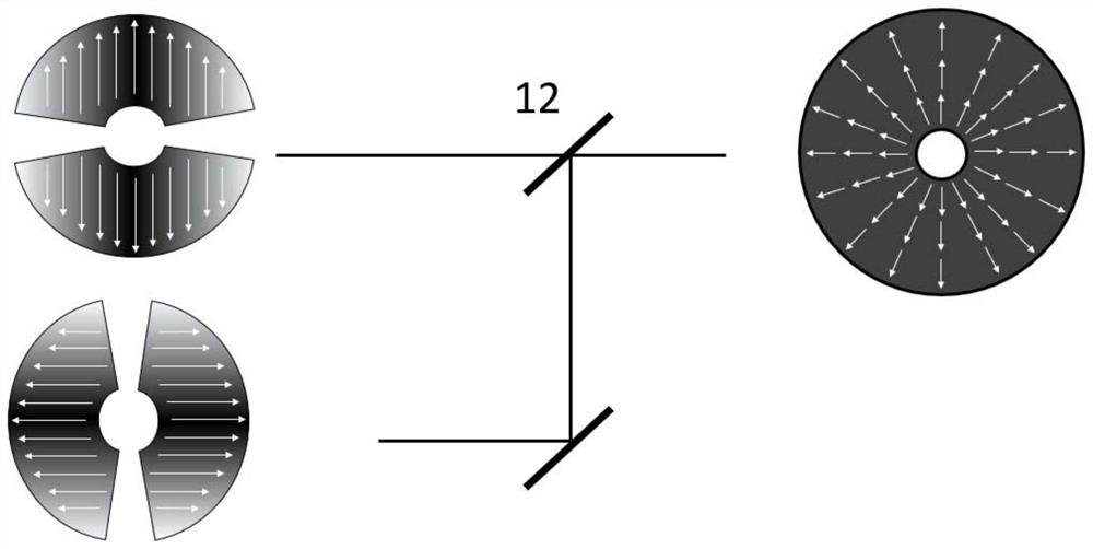
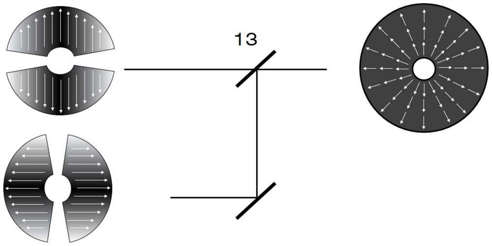
[0025] like figure 1 As shown, the present invention is a radially or angularly polarized laser device based on optical parametric chirped pulse amplification, including a femtosecond laser seed source 1, a stretcher 2, a wavelength conversion device 3, a high-energy picosecond laser 4, a vortex Wave rotation plate 5, signal light beam splitter 6, pump light beam splitter 7, pump light dichroic mirror 8, first nonlinear amplification crystal 9, compressor 10, delayer 11, half-wave plate 12 and beam combiner Mirror 13.

[0026] The femtosecond laser seed source 1 generates a beam of high-energy...


PUM


Abstract

A radially or angularly polarized laser device based on optical parametric chirped pulse amplification, using a picosecond laser as a pump source, and radially or angularly polarized light as a seed source, which are divided into two beams by a beam splitter , combined and then input into the nonlinear amplifying crystal to obtain two beams of high-energy partially radially or angularly polarized light. Two beams of high-energy partially radially or angularly polarized light pass through the compressor, one beam uses a half-wave plate to rotate the polarization direction by 90°, and the other beam of high-energy non-uniform femtosecond radially or angularly polarized light uses a beam combiner Be bundled. The present invention can effectively realize the amplification of radially or angularly polarized light by using OPCPA to amplify the two paths of radially or angularly polarized light respectively and then combine them, and better maintain the properties of radially or angularly polarized light. Thus, a beam of high-energy femtosecond radially or angularly polarized light is obtained. The invention can effectively solve the problem that traditional OPCPA cannot be amplified due to uneven polarization directions of radially or angularly polarized light, and realize high-energy radially or angularly polarized laser output.

Description

technical field [0001] The invention relates to the field of ultrafast laser technology, in particular to a radially or angularly polarized laser device based on optical parametric chirped pulse amplification. Background technique [0002] Radial or angularly polarized light is a kind of spatially non-uniform polarized light, the polarization state is different in different positions in space, and the polarization state distribution of the cross-section of the beam presents an axisymmetric or circular distribution, and the center position is caused by a phase singularity in the center of the spot The amplitude of the electric field is zero, and the intensity of the light spot presents a hollow ring distribution. Radially or angularly polarized light has many potential applications due to its unique polarization and intensity distribution characteristics, including particle trapping, high-precision metal material processing, super-resolution microscopy, surface plasmon excita...

Claims


Application Information

Patent Timeline
Patent Type & Authority Patents(China)
IPC IPC(8): H01S3/00H01S3/08
CPCH01S3/0071H01S3/0085H01S3/08004H01S3/08054
Inventor 钱俊宇彭宇杰冷雨欣李儒新李妍妍黎文开邵蓓捷吕欣林冯壬誉
Owner SHANGHAI INST OF OPTICS & FINE MECHANICS CHINESE ACAD OF SCI
Why Eureka
Try Eureka