Multistage granulation equipment for ceramic pug

A technology of ceramic mud and granulation equipment, which is applied in the direction of ceramic molding machines and manufacturing tools, which can solve the problems of reducing the efficiency of friction granulation, reducing the speed of equipment friction granulation, and sticking through holes, so as to overcome the problems of granulation The effect of low efficiency, improving drying speed and saving drying cost

Pending Publication Date: 2021-04-06
FOSHAN LANZHIJING SCI & TECH CO LTD
View PDF0 Cites 4 Cited by
  • Summary
  • Abstract
  • Description
  • Claims
  • Application Information

AI Technical Summary

Problems solved by technology

[0007] 1. When the existing equipment is granulating, the size of the mud on the sieve ranges from tiny powder particles to about 5cm of mud. The size of these mud is different from the sieve hole diameter of the sieve. It is huge, so it needs to be lifted many times before it can be broken into a size suitable for friction granulation by the breaking hammer, which reduces the efficiency of the entire friction granulation;
[0008] 2. The dryness of the ceramic mud to be treated is relatively high, and it is only suitable for ceramic mud with a water content of not more than 10%.
When the water content of the ceramic mud is high, since the sieve holes on the arc-shaped screen are only 0.5-1 mm in diameter, the ceramic mud with high water content is easy to paste the through holes, which reduces the friction of the equipment for granulation. The speed cannot even continue friction granulation;

Method used


Image

  • Multistage granulation equipment for ceramic pug
  • Multistage granulation equipment for ceramic pug
  • Multistage granulation equipment for ceramic pug

Examples


Embodiment 1

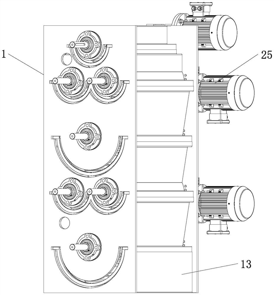
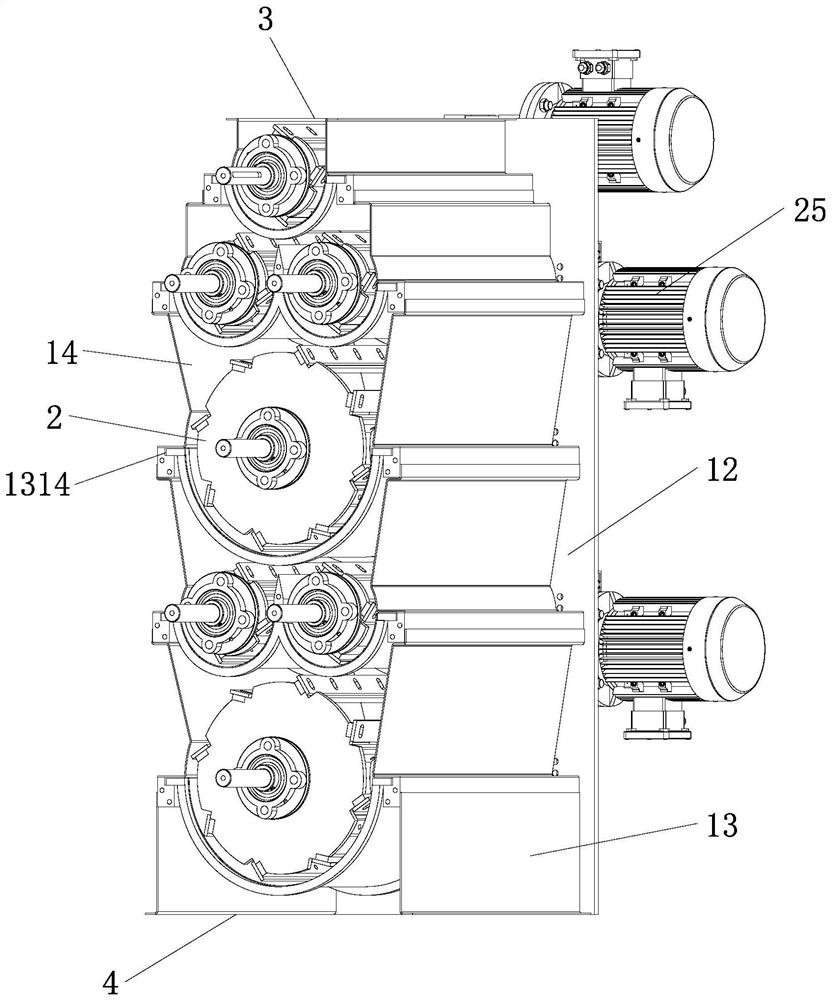
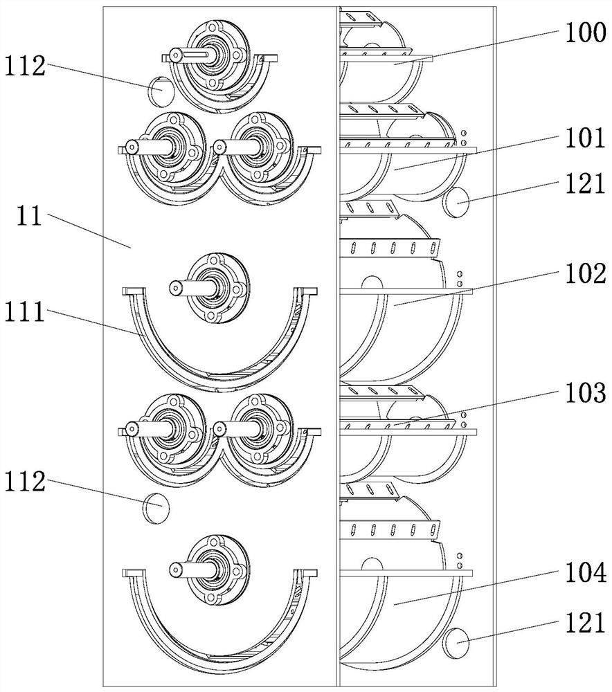
[0034] Such as Figure 1 to Figure 4 The shown multi-stage granulation equipment for ceramic mud includes a granulation bin 1. The overall shape of the granulation bin 1 is cuboid, and the interior is hollow. It includes a left side plate 11, a right side plate 12, a front baffle plate 13 and tailgate14. At least two friction granulation layers are arranged in the granulation bin 1, and at least one friction granulation assembly 2 is arranged on each friction granulation layer. In this embodiment, the granulation bin 1 is divided into the first friction granulation layer 100, the second friction granulation layer 101, the third friction granulation layer 102, the fourth friction granulation layer 103 and the fifth friction granulation layer from top to bottom. Friction granulation layer 104, wherein the number of friction granulation components 2 in odd-numbered friction granulation layers, that is, the first, third, and fifth friction granulation layers, is 1, and even-numbe...

Embodiment 2

[0044] The difference between this embodiment and the first embodiment is that: the granulation bin 1 is provided with more than one air outlet 112, and the air outlet 112 is arranged on the left side plate 11, and the air outlet 112 is connected with the exhaust fan through a pipe. A negative pressure zone is formed in the granulation bin 1 by exhausting the air.

[0045] When the water content of the ceramic mud to be processed is 8% to 10% (that is, the water content of the ceramic powder particles that are finally used to make bricks), and the water content of a single ceramic mud is relatively uniform. Since this kind of ceramic mud is relatively dry, fine powder with a mesh number less than 120 mesh will be formed during the friction granulation process. These fine powders are too fine to be used in the subsequent distributing process, so they need to be removed.

[0046] During the process of friction granulation, when the scraper 22 rotates, it will disturb the airflow...

Embodiment 3

[0050] The difference between this embodiment and the first embodiment is that: the granulation bin 1 is provided with more than one air inlet 121 and air outlet 112, and the air outlet 112 and the air inlet 121 are respectively connected to the exhaust fan and the blower through pipes.

[0051] In this example, if image 3 As shown, there are two air outlets 112 and two air inlets 121 respectively, and they are respectively opened on the left side panel 11 and the right side panel 12 . Wherein the air inlet 121 is arranged respectively under the arc-shaped screen cloth 23 of the second and the fifth friction granulation layer; below. The number of air inlets 121 and air outlets 112 can be increased or decreased as required, and the positions of the air inlets 121 and 112 can be set so as to facilitate the sufficient flow of the airflow in the granulation bin 1 .

[0052] Hot air or dry air can be passed into the air inlet 121 .

[0053] When the water content of the cerami...


PUM

PropertyMeasurementUnit
particle diameteraaaaaaaaaa
water contentaaaaaaaaaa

Abstract

The invention relates to the technical field of ceramic powder processing equipment, in particular to multistage granulation equipment for ceramic pug. The multistage granulation equipment for the ceramic pug comprises a granulation bin, wherein at least two friction granulation layers are arranged in the granulation bin; at least one friction granulation assembly is arranged on each friction granulation layer; and the pore diameter of each sieve pore of the friction granulation assembly at the lower layer is smaller than the pore diameter of each sieve pore of the friction granulation assembly at the upper layer corresponding to the friction granulation assembly at the lower layer. According to the multistage granulation equipment for the ceramic pug provided by the invention, the multiple friction granulation layers are arranged, and the sizes of powder particles prepared by the friction granulation assemblies of different friction granulation layers are reduced layer by layer, so that the problem of low granulation efficiency of existing single-layer granulation equipment is solved; in addition, dry air or hot air flow is introduced into the granulation bin through the air inlet, so that the mobility and / or the temperature of the air flow in the granulation bin are / is improved, and the powder particles are dried; and due to the fact that the specific surface area of the granulated particles is large, the drying speed is high, the drying cost is low, the surface viscosity of the dried powder particles is reduced, and the dried powder particles can fall off from the sieve pores easily.

Description

technical field [0001] The invention relates to the technical field of ceramic powder processing equipment, in particular to multistage granulation equipment for ceramic mud. Background technique [0002] In order to solve the problems of high energy consumption, serious pollution, and high production cost caused by the use of a spray drying tower to dry ceramic slurry, a Chinese invention patent application with application number 2019102196264 discloses a ceramic wet low-temperature powder-making process. Through dehydration treatment, low temperature drying treatment, crushing and granulation treatment of the mud, the obtained dry powder particles have the characteristics of low water content. This process does not need to consume too much combustion energy while maintaining the efficiency of ceramic powder making , greatly reduce the energy consumption of the ceramic production process, improve production efficiency, effectively reduce pollutants and greatly reduce the p...

Claims


Application Information

Patent Timeline
Patent Type & Authority Applications(China)
IPC IPC(8): B28B1/00B28B11/24
CPCB28B1/00B28B11/243
Inventor 李金华林庆生
Owner FOSHAN LANZHIJING SCI & TECH CO LTD
Why Eureka
Try Eureka