Cement conveying equipment with anti-solidification vibration mechanism

A vibration mechanism and conveying equipment technology, which is applied in the direction of conveyors, conveyor objects, cement mixing devices, etc., can solve the problems of ineffective prevention of cement solidification, affecting normal cement transportation, and low cement transportation efficiency, so as to prevent cement solidification , It is not easy to solidify, and the effect of improving the conveying efficiency

Pending Publication Date: 2021-04-06
陈玉兰
View PDF12 Cites 3 Cited by
  • Summary
  • Abstract
  • Description
  • Claims
  • Application Information

AI Technical Summary

Problems solved by technology

[0004] When cement is in use, cement conveying equipment is often needed to convey cement. The current cement conveying equipment cannot effec

Method used


Image

  • Cement conveying equipment with anti-solidification vibration mechanism
  • Cement conveying equipment with anti-solidification vibration mechanism
  • Cement conveying equipment with anti-solidification vibration mechanism

Examples


Embodiment 1

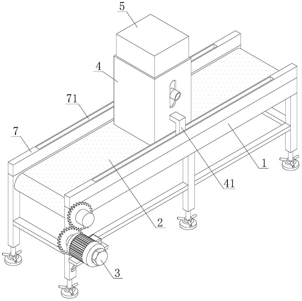
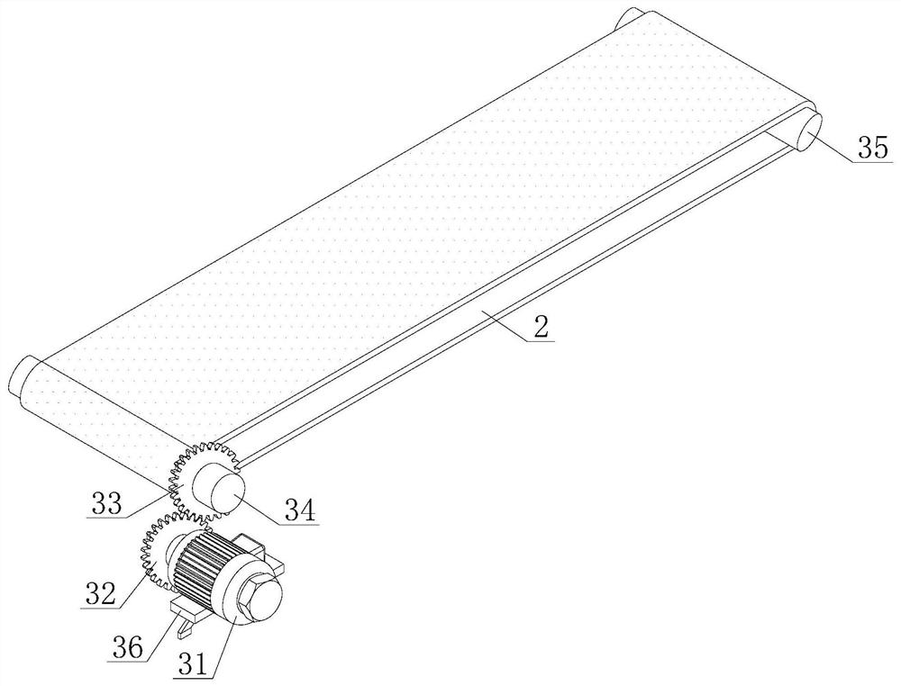
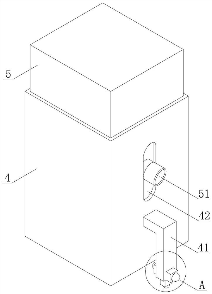
[0031] refer to figure 1 , a cement conveying device with an anti-solidification vibration mechanism, including a frame 1, a conveyor belt 2 is arranged on the upper end of the frame 1, and the conveyor belt 2 is transmitted by a drive mechanism 3, and the drive mechanism 3 drives the conveyor belt 2 to rotate, and the conveyor belt 2 is rotated by the rotating The conveyor belt 2 can drive the conveying box 4 to move steadily and smoothly on the guide seat 7 under the guidance of the guiding mechanism 41. The movement of the conveying box 4 can make the cement box 5 also move accordingly, and the cement box 5 is transported through the moving cement box. , conveying box 4 is installed on the conveyor belt 2, and the upper end of conveying box 4 is provided with cement box 5, and cement box 5 is positioned at the inner side of conveying box 4, and the lower end of cement box 5 is provided with mud discharge pipe 51, and mud discharge pipe 51 passes through The delivery box 4 e...

Embodiment 2

[0037] refer to Figure 8 , a cement conveying device with an anti-solidification vibration mechanism, including a frame 1, a conveyor belt 2 is arranged on the upper end of the frame 1, and the conveyor belt 2 is transmitted by a drive mechanism 3, and the drive mechanism 3 drives the conveyor belt 2 to rotate, and the conveyor belt 2 is rotated by the rotating The conveyor belt 2 can drive the conveying box 4 to move steadily and smoothly on the guide seat 7 under the guidance of the guiding mechanism 41. The movement of the conveying box 4 can make the cement box 5 also move accordingly, and the cement box 5 is transported through the moving cement box. , conveying box 4 is installed on the conveyor belt 2, and the upper end of conveying box 4 is provided with cement box 5, and cement box 5 is positioned at the inner side of conveying box 4, and the lower end of cement box 5 is provided with mud discharge pipe 51, and mud discharge pipe 51 passes through The delivery box 4 ...


PUM


Abstract

The invention discloses cement conveying equipment with an anti-solidification vibration mechanism, and belongs to the technical field of cement conveying. The cement conveying equipment comprises a machine frame, a conveying belt is arranged at the upper end of the machine frame, the conveying belt is conveyed by a driving mechanism, a conveying box is mounted on the conveying belt, a cement box is arranged at the upper end of the conveying box, the cement box is located on the inner side of the conveying box, an anti-solidification vibration mechanism is arranged on the inner side of the lower end of the conveying box, and the cement box vibrates in the conveying box through the anti-solidification vibration mechanism. According to the cement conveying equipment with the anti-solidification vibration mechanism, the cement box can vibrate in the conveying box through continuous ascending and descending of a lifting plate, and cement solidification can be prevented; and meanwhile, cement can be stirred through rotating stirring blades, cement solidification can be prevented again, so that the cement is not prone to being solidified in the conveying process, normal conveying of the cement cannot be affected, and then the conveying efficiency of the cement can be improved.

Description

technical field [0001] The invention relates to the technical field of cement conveying, in particular to cement conveying equipment with an anti-solidification vibration mechanism. Background technique [0002] Cement: powdery hydraulic inorganic gelling material. After adding water and stirring, it becomes a slurry, which can be hardened in air or in water, and can firmly bind sand, stone and other materials together. [0003] In the early years the mixture of lime and volcanic ash is very similar to lime pozzolanic cement, use it to glue concrete which made of crushed stone. After hardening, the cement not only has high strength, but also can resist the erosion of fresh water or salt water. For a long time, as an important cementing material, it is widely used in civil engineering, water conservancy, national defense and other projects. [0004] When cement is in use, cement conveying equipment is often needed to convey cement. The current cement conveying equipment can...

Claims


Application Information

Patent Timeline
IPC IPC(8): B28C5/48B65G15/30B65G23/24B65G41/00
CPCB28C5/48B28C5/485B65G15/30B65G23/24B65G41/00B65G2201/0258
Inventor 陈玉兰
Owner 陈玉兰
Why Eureka
Try Eureka