
Two-phase flow simulation method of solid rocket engine under flight overload

A solid rocket, simulation method technology, applied in design optimization/simulation, computer-aided design, special data processing applications, etc., can solve the problem of inability to effectively evaluate the impact of overload on adiabatic layer, inability to establish engine correspondence, inability to achieve simulation calculations, etc. problem, to achieve the effect of convenient application, high accuracy and wide application range

Pending Publication Date: 2021-04-06
BEIJING RES INST OF MECHANICAL & ELECTRICAL TECH
View PDF5 Cites 4 Cited by
  • Summary
  • Abstract
  • Description
  • Claims
  • Application Information

AI Technical Summary

Problems solved by technology

One is to test run with a small engine on the ground, or use a rotating engine to achieve the purpose of centrifugal acceleration simulation overload, or use a small engine with a turning ring to simulate the direct erosion of the gas flow on the insulation layer, but the former cannot remove the influence of the Coriolis force, and the latter The latter cannot establish a corresponding relationship with the real engine at present, and neither of the two methods can effectively evaluate the possible impact of overload on the thermal insulation layer
The second is to carry out preliminary regularity research through two-phase flow calculation and simulation, or assume a model through commercial software, or realize the research on the behavior of condensed phase particles through programming and other means, but the former has too many assumptions, and the accuracy of application in engineering practice is too low, the latter is only an approximation method for the two-dimensional model, and it is not yet possible to achieve effective simulation calculations for the flow field in the combustion chamber of the engine with a complex three-dimensional structure

Method used


Image

  • Two-phase flow simulation method of solid rocket engine under flight overload
  • Two-phase flow simulation method of solid rocket engine under flight overload
  • Two-phase flow simulation method of solid rocket engine under flight overload

Examples


Embodiment Construction

[0034] Specific embodiments of the present invention will be described in detail below. In the following description, for purposes of explanation and not limitation, specific details are set forth in order to provide a thorough understanding of the invention. It will be apparent, however, to one skilled in the art that the present invention may be practiced in other embodiments that depart from these specific details.

[0035] It should be noted here that, in order to avoid obscuring the present invention due to unnecessary details, only the device structures and / or processing steps closely related to the solution of the present invention are shown in the drawings, and the steps related to the present invention are omitted. Other details that don't really matter.

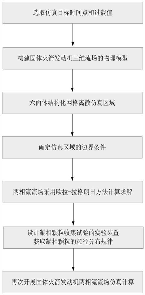
[0036] The invention provides a two-phase flow simulation method of a solid rocket motor under flight overload, the main process is as follows figure 1 shown, including the following steps:

[0037] S1: According...


PUM


Abstract

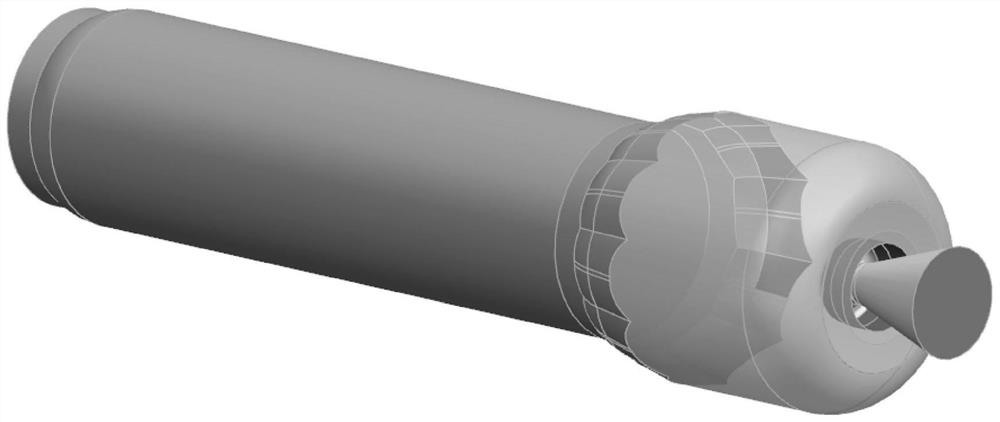
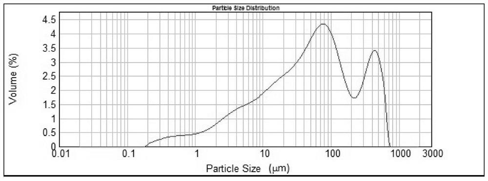
The invention discloses a two-phase flow simulation method for a solid rocket engine under flight overload, and the method comprises the steps: (1) selecting a target time point and an overload value for research according to the time and overload conditions in a flight trajectory; (2) constructing a physical model of a three-dimensional flow field of the solid rocket engine; (3) discretizing the simulation area by adopting a hexahedral structured grid; (4) regarding a combustion product of the propellant as a combustion gas-phase particle and a combustion condensed-phase particle, and setting simulation boundary conditions; (5) calculating and solving the flow field of the two-phase flow by adopting an Euler-Lagrange method; (6) designing a condensed phase particle collection test experiment device, and obtaining a particle size distribution rule of condensed phase particles; and (7) carrying out simulation calculation on the flow field of the two-phase flow of the solid rocket engine again to obtain the movement and distribution rule of the particles in the flow field. The method is high in simulation calculation accuracy, wide in application range, low in technical difficulty, high in engineering feasibility and capable of being conveniently applied to model development.

Description

technical field [0001] The invention belongs to the technical field of solid rocket motors, and relates to a flow field simulation calculation method of a solid rocket motor, in particular to a two-phase flow simulation method of a flow field in a combustion chamber of an engine under flight overload conditions. Background technique [0002] During the flight process of the booster phase of the near-space vehicle, the ballistic trajectory needs to be depressed to meet the requirements of the handover point. As the propulsion force of the vehicle, the solid rocket motor needs to face a long-term continuous lateral overload environment during the working process. The condensed phase particles in the propellant combustion products are affected by the overload condition and converge into a particle flow in the flow field of the combustion chamber, which impacts on the heat insulation layer, resulting in a strong erosion and ablation effect, increasing the load capacity of the hea...

Claims


Application Information

Patent Timeline
Patent Type & Authority Applications(China)
IPC IPC(8): G06F30/28G06F30/17G06F113/08G06F119/14
CPCG06F30/28G06F30/17G06F2113/08G06F2119/14
Inventor 常桁陶善治许琪冯芒
Owner BEIJING RES INST OF MECHANICAL & ELECTRICAL TECH
Learn More