Supercharge Your Innovation With Domain-Expert AI Agents!

Apparatus and method for reduction of particle contamination by bias voltage

A bias voltage, voltage source technology, applied in circuits, discharge tubes, electrical components, etc., can solve problems such as being easily hit by ions

Pending Publication Date: 2021-04-06
ADVANCED ION BEAM TECHNOLOGY INC
View PDF0 Cites 0 Cited by
  • Summary
  • Abstract
  • Description
  • Claims
  • Application Information

AI Technical Summary

Problems solved by technology

These internal components are susceptible to being struck by ions during the ion implantation procedure

Method used


Image

  • Apparatus and method for reduction of particle contamination by bias voltage
  • Apparatus and method for reduction of particle contamination by bias voltage
  • Apparatus and method for reduction of particle contamination by bias voltage

Examples


Embodiment Construction

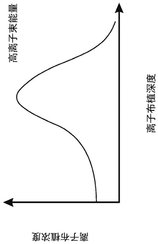
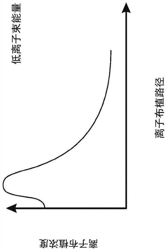
[0059] The physical mechanism of the problem to be solved by the present invention can be briefly described as follows. The ion implantation depth (doping depth) is proportional to the ion beam energy (doping energy), and the ion implantation concentration (doping concentration) is correspondingly proportional to the ion implantation current. refer to Figure 1A to Figure 1B Shows how ion implant depth and ion implant concentration vary with different ion beam energies. Reasonably, when the energy of the ion beam is low enough, the distribution of implanted ions will be largely concentrated in the vicinity of the surface of the implanted component. Therefore, not only the shallower part of the implanted component is strongly damaged due to the presence of a large number of implanted ions, but also a certain number of particles are stripped from the implanted component and float into the vacuum environment where the wafer is held for ion implantation . For example, the exfol...


PUM


Abstract

The invention provides a bias voltage to the component (such as the Faraday cup) for reducing the generation of particles, such as the implanted ions and / or the combination of the implanted ions and the material of the component, and preventing particles peeling away the component. The strength of the biased voltage should not significantly affect the implantation of ions into the wafer and should significantly prevent the emission of radiation and / or electrons away the biased component. How to provide and adjust the biased voltage is not limited, both the extra voltage source and the amended Pre-Amplifier are acceptable. Moreover, due to the electric field generated by the Faraday cup is modified by the biased voltage, the ion beam divergence close to the Faraday cup may be reduced such that the potential difference between the ion beam measured by the profiler and received by the Faraday cup may be minimized.

Description

technical field [0001] The present invention relates to improvements to ion implanters and ion implants, and in particular to improvements in reducing particle contamination by using bias voltages in low energy ion implants. Background technique [0002] Ion implantation technology has been widely used to manufacture modern products, such as integrated circuits, volatile or non-volatile memory, flat panel displays, and solar cells, etc. Therefore, there is a strong need to continuously improve the structure of the ion implanter so as to be suitable for different ion implantation procedures. [0003] In recent years, the demand for low-energy ion implantation, such as ion implantation with ion energy below 1000 electric volts (eV), has continued to increase. Such needs lead to a more critical need: to prevent particle contamination of internal components (internal components) that are hit by ions, for example, internal components can be Faraday cups (Faraday cups), chucks (C...

Claims


Application Information

Patent Timeline
Patent Type & Authority Applications(China)
IPC IPC(8): H01J37/317H01L21/67
CPCH01J37/3171H01L21/67011H01J2237/022H01J2237/31705H01J2237/24535H01J2237/24564H01J2237/24405H01J37/244H01J37/026H01J37/08H01J37/248H01J37/32715H01J37/243
Inventor 胡邵喻
Owner ADVANCED ION BEAM TECHNOLOGY INC
Features
  • R&D
  • Intellectual Property
  • Life Sciences
  • Materials
  • Tech Scout
  • Unparalleled Data Quality
  • Higher Quality Content
  • 60% Fewer Hallucinations
Learn More