Vehicle structure resistant to direct impact and manufacturing method
A manufacturing method and vehicle technology, applied to the substructure, superstructure, vehicle parts, etc., to achieve the effect of reducing the number of body parts, reducing the number and weight, and improving safety performance
- Summary
- Abstract
- Description
- Claims
- Application Information
AI Technical Summary
Problems solved by technology
Method used
Image
Examples
Embodiment 1
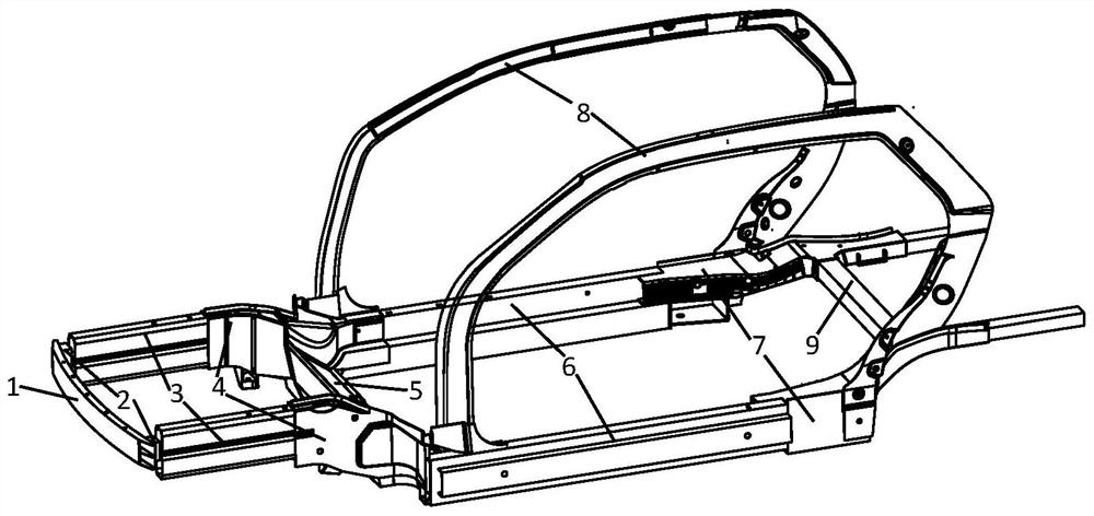
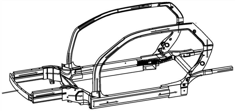
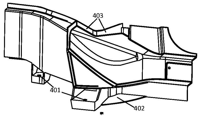
[0047] Figure 1-4 A vehicle structure for resisting frontal collision is shown, including an anti-collision beam 1 located at the front end of the vehicle body; energy-absorbing boxes 2 installed at both ends of the back of the anti-collision beam 1; front longitudinal beams 3 installed at the back of the energy-absorbing box 2; Including the front connecting piece 4 installed at the tail end of the front longitudinal beam 3; the firewall beam 5 installed between the two front connecting pieces 4, the threshold beam 6 installed at the rear end of the front connecting piece 4; the rear connection installed at the rear end of the threshold beam 6 Part 7; the side wall frame 8 installed on the top of the front connecting part 4 and the top of the rear connecting part 7 and the floor rear beam 9 installed between the two rear connecting parts 7; The energy box 2, the horizontal closed loop surrounded by the front longitudinal beam 3 and the fire wall crossbeam 5;
[0048] Due to...
Embodiment 2
[0057] The present invention also relates to the above-mentioned manufacturing method, specifically comprising the following steps:
[0058] S1: Manufacture the energy-absorbing box 2, front longitudinal beam 3, firewall beam 5, sill beam 6, and side wall frame 8 by extrusion molding process; manufacture front anti-collision beam 1 and side wall frame 8 by extrusion stretch-bending process ; The front connector 4 and the rear connector 7 are manufactured by a casting process;
[0059] S2: Use the parts formed in step S1 to assemble the vehicle body.
[0060] In this embodiment, in step S1, the extrusion molding process includes the following steps:
[0061] (1) According to the cross-sectional shape of the part to be extruded, prepare the corresponding extrusion die, and fasten the extrusion die to the port of the extrusion equipment;
[0062] (2) Soften the material, heat the aluminum alloy ingot to 380-440°C, and laser cut the aluminum material according to the required si...
Embodiment 3
[0080] exist Figure 1-4 Among them, the present invention provides a vehicle structure that resists frontal collisions, and the structure includes a front anti-collision beam 1, an energy-absorbing box 2, a front longitudinal beam 3, a front connector 4, a firewall beam 5, a threshold beam 6, and a rear connector 7 , side wall frame 8, floor rear beam 9.
[0081] In this embodiment, the energy-absorbing box 2 , the front longitudinal beam 3 , the front connector 4 , the sill beam 6 , the rear connector 7 , and the side wall frame 8 are all left-right symmetrical structures about the central axis of the vehicle.
[0082]In this embodiment, the front anti-collision beam 1 is located at the forefront of the structure, and behind it is a symmetrical energy-absorbing box 2, and the energy-absorbing box 2 is welded to the front anti-collision beam 1 and its coaxial rear front by CMT. The longitudinal beam 3 is connected; the rear part of the front longitudinal beam 3 is the front ...
PUM
 Abstract
Description
Claims
Application Information
 - R&D
- Intellectual Property
- Life Sciences
- Materials
- Tech Scout
- Unparalleled Data Quality
- Higher Quality Content
- 60% Fewer Hallucinations
Browse by: Latest US Patents, China's latest patents, Technical Efficacy Thesaurus, Application Domain, Technology Topic, Popular Technical Reports.
© 2025 PatSnap. All rights reserved.Legal|Privacy policy|Modern Slavery Act Transparency Statement|Sitemap|About US| Contact US: help@patsnap.com


