Vehicle control system
A vehicle control system, vehicle technology, applied in transmission systems, vehicle components, digital transmission systems, etc., can solve problems such as difficult to replace hardware
- Summary
- Abstract
- Description
- Claims
- Application Information
AI Technical Summary
Problems solved by technology
Method used
Image

Examples
no. 1 approach
[0025] The first embodiment of the present invention and the accompanying Figure 1 Same as explanation.
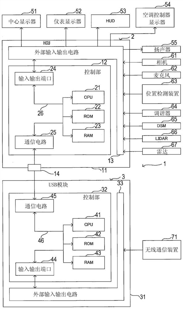
[0026] The vehicle control system 1 of this embodiment is mounted on a vehicle, such as figure 1 As shown, a human-machine interface control device 2 (hereinafter referred to as HCU2 ) and a USB module 3 are provided. HCU is the abbreviation of Human Machine Interface Control Unit (human-machine interface control unit). USB is the abbreviation of Universal Serial Bus (Universal Serial Bus).
[0027] The HCU 2 is, for example, a semiconductor integrated circuit composed of SoC, and includes a housing 11 , a control unit 12 , and an external input / output circuit 13 for inputting and outputting signals between the outside of the HCU 2 and the control unit 12 . SoC is the abbreviation of System on a Chip (system on a chip).
[0028] The casing 11 is a metal member formed in a box shape, and accommodates the control unit 12 and the external input / output circuit 13 inside. ...
no. 2 approach
[0091] Hereinafter, the second embodiment of the present invention and the accompanying Figure 1 Same as explanation. In addition, in 2nd Embodiment, the part which differs from 1st Embodiment is demonstrated. Common structures are assigned the same reference numerals.
[0092] The vehicle control system 1 of the second embodiment differs from the first embodiment in the following points: Figure 5 As shown, the position detection device 63 is not connected to the HCU2, but is connected to the USB module 3.
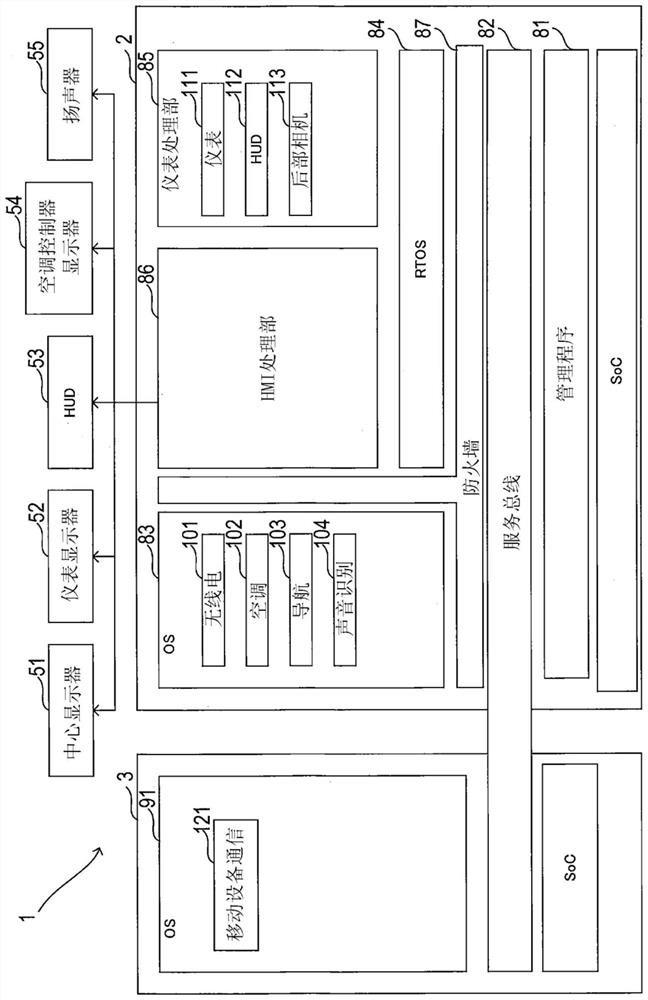
[0093] Data indicating the position detected by the position detection device 63 is input to the OS 91 . The navigation application installed in OS91 creates the display data for displaying the center display 51 based on the input positional data. Furthermore, the navigation application outputs the created display data to the HMI processing unit 86 via the service bus 82 . The HMI processing unit 86 outputs display data input from the OS 91 to the center display 51 ...
no. 3 approach
[0095] Hereinafter, the third embodiment of the present invention and the accompanying Figure 1 Same as explanation. In addition, in 3rd Embodiment, the part which differs from 2nd Embodiment is demonstrated. Common structures are assigned the same reference numerals.
[0096] The vehicle control system 1 of the third embodiment differs from the second embodiment in the following points: Figure 6 As shown, the microphone 62 is not connected to the HCU2, but is connected to the USB module 3.
[0097] Data representing the sound detected by the microphone 62 is input to the OS 91 . The voice recognition application mounted on the OS 91 determines an output voice to be output from the speaker 55 based on the input voice data, and outputs data indicating the determined output voice to the OS 83 via the service bus 82 . OS83 outputs the data input from OS91 to HMI processing part 86 . The HMI processing unit 86 outputs the data input from the OS 83 to the speaker 55 . A bro...
PUM
 Abstract
Description
Claims
Application Information
 - R&D Engineer
- R&D Manager
- IP Professional
- Industry Leading Data Capabilities
- Powerful AI technology
- Patent DNA Extraction
Browse by: Latest US Patents, China's latest patents, Technical Efficacy Thesaurus, Application Domain, Technology Topic.
© 2024 PatSnap. All rights reserved.Legal|Privacy policy|Modern Slavery Act Transparency Statement|Sitemap