Combustor for lower combustion chamber of annular sleeve kiln and flameless combustion method

A technology of annular sleeve and combustion chamber, which is applied in the direction of combustion method, gas fuel burner, burner, etc., to achieve the effects of inhibiting the formation of nitrogen oxides, improving the thermal condition of the furnace, and reducing the formation of NOx

Active Publication Date: 2021-04-13
江苏宇力节能科技有限公司
View PDF11 Cites 1 Cited by
  • Summary
  • Abstract
  • Description
  • Claims
  • Application Information

AI Technical Summary

Problems solved by technology

[0007]Technical purpose: Aiming at the defects in the prior art that the calorific value of the gas cannot be adjusted while suppressing the generation of nitrogen oxides, the present invention discloses a The burner and flameless combustion method of the combustion chamber under the kiln, the gas is sent into the combustion chamber through the burner through two independent interfaces, and the fuel and air are staged for combustion, and the primary combustion is oxygen deficient combustion to reduce nitrogen oxides , the secondary combustion is flameless combustion to suppress the formation of nitrogen oxides

Method used


Image

  • Combustor for lower combustion chamber of annular sleeve kiln and flameless combustion method
  • Combustor for lower combustion chamber of annular sleeve kiln and flameless combustion method
  • Combustor for lower combustion chamber of annular sleeve kiln and flameless combustion method

Examples


Embodiment Construction

[0037]The present invention will be further described and explained below with reference to the accompanying drawings.

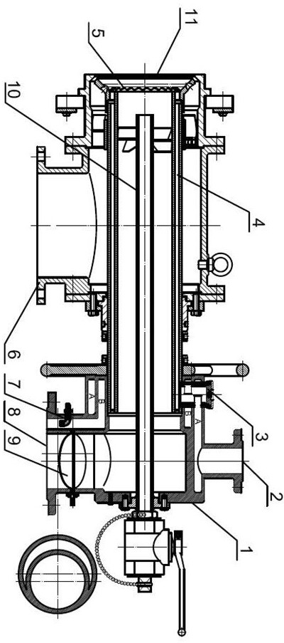
[0038]The present invention discloses a combustor and flameless combustion method for a combustion chamber under annular sleeve kiln. In the present embodiment,figure 1 As shown, a burner for the combustion chamber under the ring sleeve kiln includes a gas joint 1, a gas nozzle 4, an air joint 6, a central tube 10, and a burner spout 11, and a central tube 10 outer peripheral set of gas nozzle 4, the center tube 10 is provided with the gas joint 1, and the other end is provided with the burner nozzle 11, and the gas joint 1 and the burner nozzle 11 communicate through the gas nozzle 4, the intake end of the gas nozzle 4 communicates with the gas joint 1, and the depth communication The burner spray port 11; the central tube 10 is provided with an air joint 6 on one side of the burner spray port 11, and the gas nozzle 4 is a sleeve structure composed of two coaxial ci...


PUM


Abstract

The invention discloses a combustor for a lower combustion chamber of an annular sleeve kiln and a flameless combustion method. The method comprises the steps: injecting first-stage air into the combustor through an air connector, and controlling the air excess coefficient of the first-stage combustion to be 0.7-0.8; introducing fuel gas into an outer ring spray pipe of a fuel gas spray pipe, conducting ignition at the same time, and enabling the fuel gas introduced into the outer ring spray pipe and the first-stage air to be subjected to first-stage oxygen-deficient combustion in the lower combustion chamber; injecting second-stage air into an exhaustion area of the first-stage air, wherein the air flow is calculated according to the fact that the total air excess coefficient of the first-stage combustion and second-stage combustion is larger than 1; opening a regulating valve, spraying the fuel gas to the combustion chamber through an inner ring spray pipe of the gas spray pipe, and conducting second-stage combustion in the lower combustion chamber; enabling first-stage combustion products to be enriched near the jet boundary of the fuel gas sprayed by the inner ring spray pipe, and combusting and diluting the second-stage air in the lower combustion chamber; and meeting high-temperature and low-oxygen conditions in a combustion area, and inhibiting generation of nitric oxide.

Description

Technical field[0001]The present invention relates to the field of annular sleeve kiln, and more particularly to a combustor and flame combustion method for a combustion chamber under annular sleeve kiln.Background technique[0002]The annular sleeve is a more advanced lime calcination device, wherein the typical structure of the underflake chamber burner of the annular sleeve kiln is known to be utharities, wherein the air and gas enter the burner from the air joint and the gas joint, respectively. There is a swirling piece in the air passage and gas channel such that both gases have tangential velocity components after leaving the spout to facilitate rapid mixing combustion of air and gas. At the same time, the rotating gas stream can form a low pressure region in the central region near the spout to return the high temperature gas generated to the spout to stabilize the flame. The disadvantage of this burner is:[0003]1. When the burner is working away from the design conditions, th...

Claims


Application Information

Patent Timeline
Patent Type & Authority Applications(China)
IPC IPC(8): F23D14/02F23D14/46F23D14/60F23D14/64
CPCF23D14/02F23D14/64F23D14/46F23D14/60Y02E20/34
Inventor 卞正培李维祥付太陆毛忠仁
Owner 江苏宇力节能科技有限公司
Why Eureka
Try Eureka