Improved jointed rock mass blasting model test vibration monitoring system and method

A jointed rock mass and model test technology, applied in geographic modeling, measuring devices, earthwork drilling and mining, etc., can solve the problem of being easily affected by electromagnetic interference, unable to realize all-round monitoring and recording of blasting vibration, and unable to capture and analyze in real time Rock mass crack evolution process and cracking mechanism and other issues

Pending Publication Date: 2021-04-13
ANHUI UNIV OF SCI & TECH
View PDF18 Cites 5 Cited by
  • Summary
  • Abstract
  • Description
  • Claims
  • Application Information

AI Technical Summary

Problems solved by technology

[0005] 1) It is impossible to capture and analyze the crack evolution process and cracking mechanism of jointed rock mass under blasting load in real time
[0006] 2) It is impossible to monitor both the impact of blast stress wave on the stability of existing jointed surrounding rock roadway and the impact of blast stress wave on the stability of jointed rock mass
[0007] 3) The traditional strain measurement technology cannot monitor and record the large deformation of the surrounding rock under the blasting load, and is easily affected by electromagnetic interference, resulting in experimental errors
[0008] 4) It is impossible to realize all-round monitoring and record the impact of blasting vibration on the existing roadway, and it is also impossible to analyze the impact of different differential blasting modes on the existing roadway

Method used


Image

  • Improved jointed rock mass blasting model test vibration monitoring system and method
  • Improved jointed rock mass blasting model test vibration monitoring system and method
  • Improved jointed rock mass blasting model test vibration monitoring system and method

Examples


Embodiment Construction

[0041] The present invention will be further described below in conjunction with accompanying drawing:

[0042] In order to make the purpose, technical solution and advantages of the present invention clearer, the following will further describe the implementation of the present invention in detail in conjunction with the accompanying drawings. It should be understood that the specific embodiments described here are only used to illustrate and explain the present invention, and are not intended to limit the present invention.

[0043] In the description of the present invention, it should be noted that the terms "center", "upper", "lower", "left", "right", "vertical", "horizontal", "inner", "outer" etc. The indicated orientation or positional relationship is based on the orientation or positional relationship shown in the drawings, and is only for the convenience of describing the present invention and simplifying the description, rather than indicating or implying that the re...


PUM


Abstract

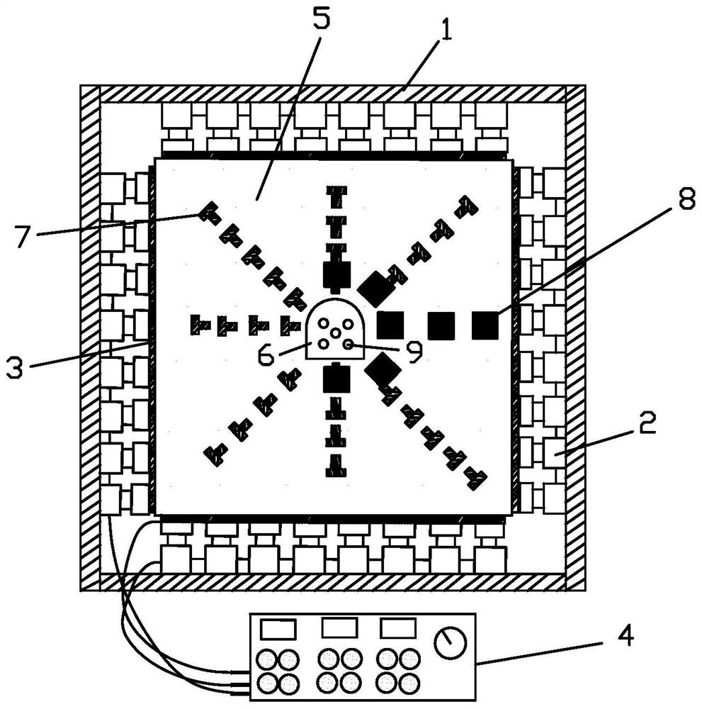
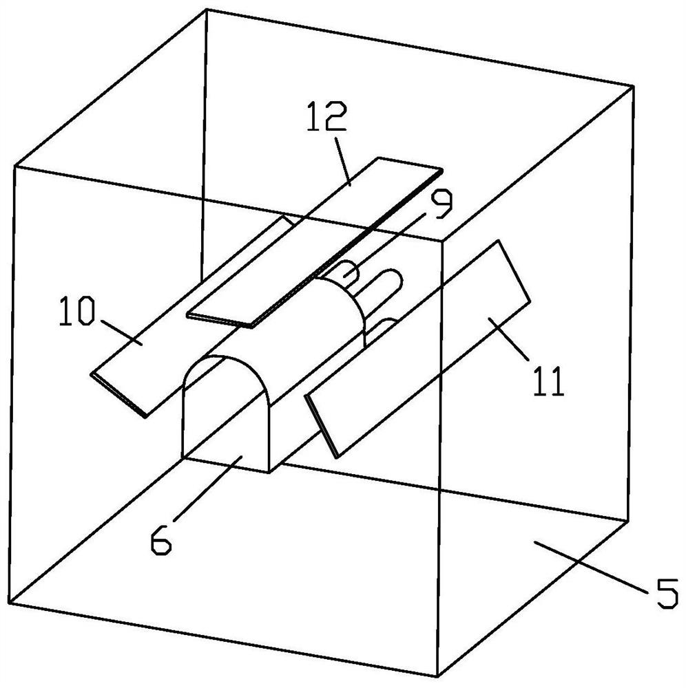
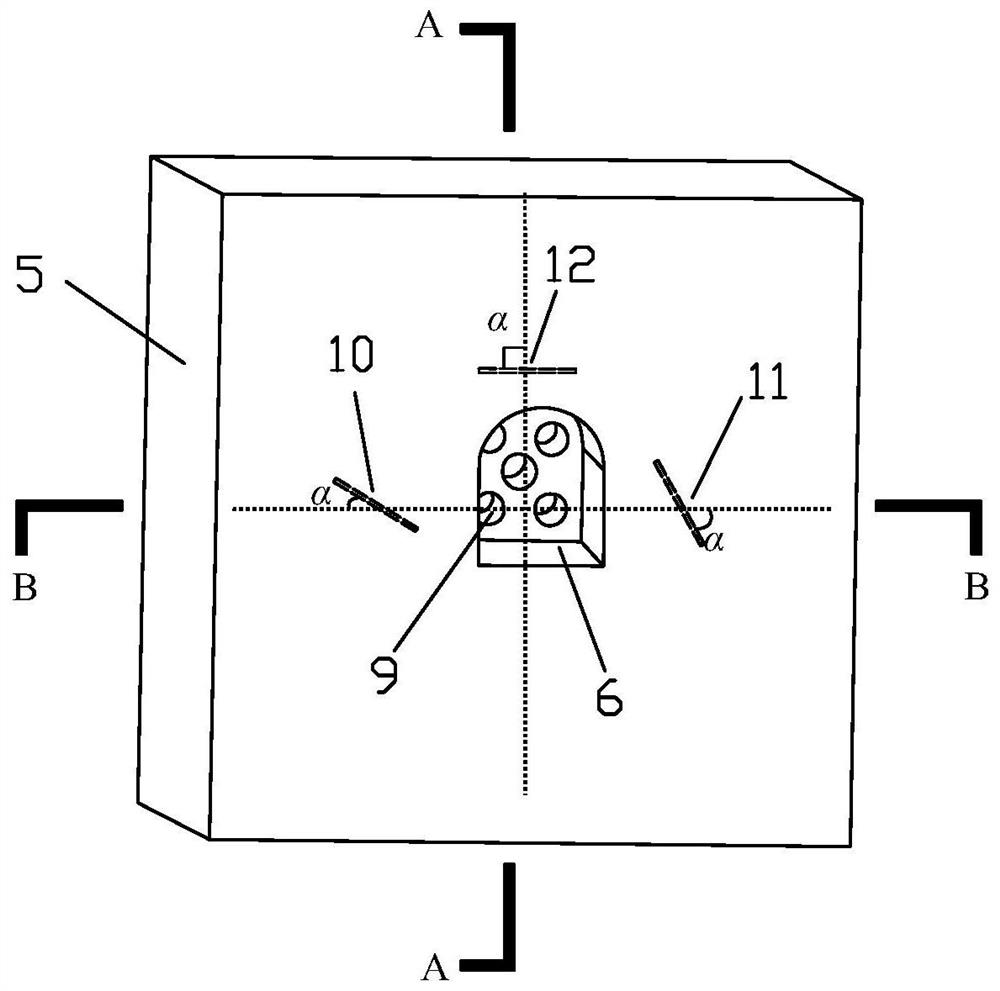
The invention belongs to the field of blasting theories and technologies and deep rock mechanics, and provides an improved jointed rock mass blasting model test vibration monitoring system and method. The improved jointed rock mass blasting model test vibration monitoring system comprises a three-way load loading subsystem, a model surface blasting vibration acquisition subsystem and a model internal dynamic stress-strain acquisition subsystem. The invention provides the improved jointed rock mass blasting model test vibration monitoring system and method, and the prepared transparent jointed rock mass blasting model and monitoring method can be used for analyzing the influence of a joint inclination angle on the propagation and attenuation rule of explosion stress waves in a jointed rock mass as well as the influence of different millisecond blasting modes on the stability of the existing roadway in the jointed rock mass, the dynamic evolution process of cracks is captured in real time, the used stress and strain measurement technology can monitor and record large deformation of surrounding rock under the blasting load effect in an omnibearing mode, and the influence of electromagnetic interference can be resisted. And the test data are more reliable and real.

Description

technical field [0001] The invention belongs to the fields of blasting theory and technology and deep rock mechanics, and in particular relates to an improved vibration monitoring system and method for blasting model tests of jointed rock masses. Background technique [0002] Blasting vibration effect is an important factor that induces dynamic instability in deep mine roadway. The research on the dynamic instability of surrounding rock in deep mine roadways under the action of blasting vibration mainly focuses on the deformation of surrounding rock in roadway under the action of blasting vibration, the deterioration of surrounding rock in roadway during the propagation of blasting vibration waves, the influence of particle vibration velocity on the stability of surrounding rock, joints Instability failure and frequency spectrum analysis of rock mass under vibration conditions. There are few studies on the mechanism of dynamic instability of surrounding rock caused by blast...

Claims


Application Information

Patent Timeline
Patent Type & Authority Applications(China)
IPC IPC(8): G01H11/08
CPCG01H11/08G01N33/24G01N2203/0066G01N3/068G01N2203/0647G01N3/313E21D9/00G01H1/00G01V1/008G01H9/004E21D9/003G01N3/066G01N2203/001G01N2203/003G01N2203/0075G01N2203/0623G01N2203/0641G01V99/005
Inventor 马芹永苏晴晴袁璞
Owner ANHUI UNIV OF SCI & TECH
Why Eureka
Try Eureka