
Novel millimeter wave anti-interference microstrip array antenna

A microstrip array and millimeter wave technology, applied in antenna, antenna coupling, antenna array, etc., can solve the problems of the influence of the amplitude and phase distribution of the feed network, the antenna interference cannot work normally, and the side lobe level of the pattern rises, etc., to achieve Effects of weak interference coupling, easy carrier conformation, and reduced gain fluctuation

Pending Publication Date: 2021-04-13
上海鲸目科技有限公司
View PDF7 Cites 1 Cited by
  • Summary
  • Abstract
  • Description
  • Claims
  • Application Information

AI Technical Summary

Problems solved by technology

The traditional shielding measures are based on the metal cavity, and the strong internal reflection crosstalk has seriously affected the amplitude and phase distribution of the feed network.
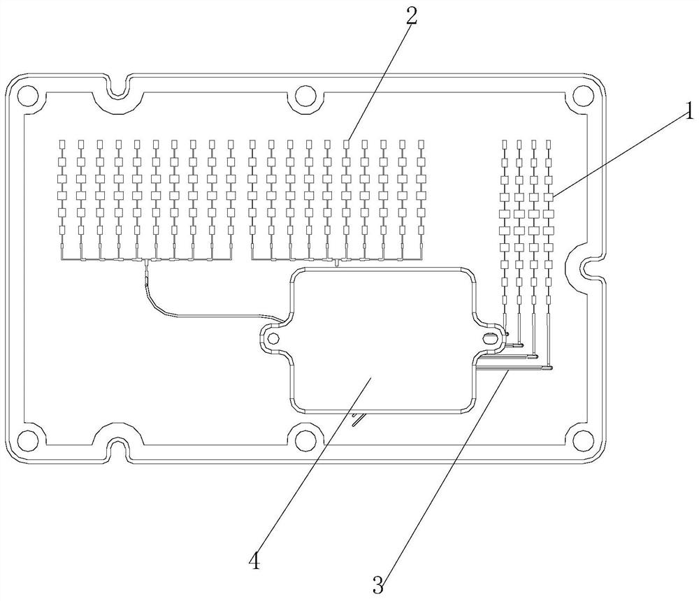
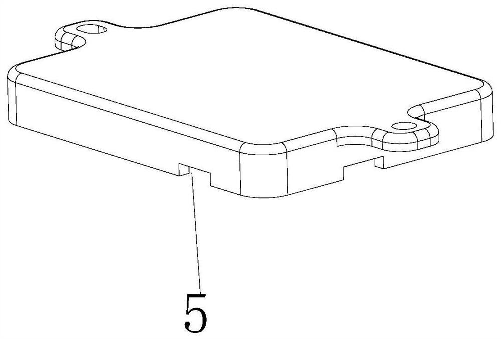
[0005] In order to solve the problem that the sidelobe level of the pattern increases and the gain decreases caused by the mutual coupling between the microstrip array antenna and the feed network, and the antenna is disturbed and cannot work normally due to the energy leakage of the active circuit and the chip, the present invention proposes a A new millimeter-wave anti-coupling interference microstrip array antenna design. The antenna feed network adopts a conformal design of plastic absorbing materials, which can effectively suppress the radiation leakage of the chip and the coupling interference between the antenna and feed systems, and will not form a metal cavity. Body reflection causes the amplitude and phase mismatch of the feed network. Compared with sponge-type absorbing materials, it is easy to install conformally, has high strength, and is not easy to deform and age.

Method used


Image

  • Novel millimeter wave anti-interference microstrip array antenna
  • Novel millimeter wave anti-interference microstrip array antenna

Examples


Embodiment Construction

[0021] The following will clearly and completely describe the technical solutions in the embodiments of the present invention with reference to the accompanying drawings in the embodiments of the present invention. Obviously, the described embodiments are only some, not all, embodiments of the present invention. Based on the embodiments of the present invention, all other embodiments obtained by persons of ordinary skill in the art without making creative efforts belong to the protection scope of the present invention.

[0022] In describing the present invention, it should be understood that the terms "center", "longitudinal", "transverse", "length", "width", "thickness", "upper", "lower", "front", " Back", "Left", "Right", "Vertical", "Horizontal", "Top", "Bottom", "Inner", "Outer", "Clockwise", "Counterclockwise", "Axial", The orientation or positional relationship indicated by "radial", "circumferential", etc. is based on the orientation or positional relationship shown in...


PUM


Abstract

The invention relates to the technical field of array antennas, and discloses a novel millimeter wave anti-interference microstrip array antenna. The antenna comprises a series-fed receiving antenna array, a series-fed transmitting antenna array and a radiation unit, and the series-fed receiving antenna array and the series-fed transmitting antenna array are arranged outside an anti-interference shielding case; and the anti-interference shielding case is internally provided with a radio frequency chip, the radio frequency chip passes through a feed network and penetrates through a feed line through hole to be electrically connected with a transmitting antenna, the radiation units adopt square microstrip patches, and the radiation units are connected with one another in series to form a microstrip array. According to the invention, the absorption efficiency is formed by the plastic wave-absorbing material loaded with carbon powder, so that the mutual coupling energy of the feed network is effectively absorbed; and by covering the chip and the peripheral active circuit, the wall thickness of the radiation interference shielding case is effectively reduced to be a quarter of the working wavelength of antenna radiation, and the influence of reflection in the cavity on the feed network can be reduced.

Description

technical field [0001] The invention relates to the technical field of array antennas, in particular to a novel millimeter-wave anti-jamming microstrip array antenna. Background technique [0002] With the improvement of the integration degree of electronic equipment, the volume of communication equipment is also becoming smaller and smaller. The microstrip antenna has the characteristics of small size, light weight, low profile, easy installation and conformal to the carrier surface, and the feed network is made together with the antenna, which is suitable for mass production with printed circuit technology. Integrating the microstrip antenna with active devices or circuits can realize a fully integrated transceiver front-end module. Therefore, microstrip antenna technology has received widespread attention and has been widely used in millimeter wave radar, communication, guidance and other fields. [0003] Compared with a single antenna unit that is difficult to meet the...

Claims


Application Information

Patent Timeline
IPC IPC(8): H01Q1/38H01Q1/50H01Q1/52H01Q17/00H01Q21/00H01Q21/06H01Q21/28
CPCH01Q1/38H01Q17/00H01Q1/52H01Q1/526H01Q1/50H01Q21/065H01Q21/28H01Q21/0006
Inventor 李振华李坤李立吴立丰王寰宇
Owner 上海鲸目科技有限公司
Learn More