Capacitor, and capacitor electrode
A technology for capacitors and positive electrodes, which is applied in the field of capacitors and electrodes for capacitors, which can solve the problems of low energy density and achieve high energy density and high durability
- Summary
- Abstract
- Description
- Claims
- Application Information
AI Technical Summary
Problems solved by technology
Method used
Image
Examples
preparation example Construction
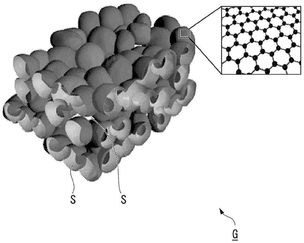
[0077] The synthesis method of the graphene porous carbon material constituting the graphene porous carbon sheet of the present embodiment includes: forming a graphene layer on the surface of nanoparticles composed of metal oxides; removing the nanoparticles composed of metal oxides and a process of heating the graphene layer covering the fine pores. For example, a single-layer to three-layer graphene is formed to cover aluminum oxide particles with an average particle diameter of 2nm to 20nm, preferably 3nm to 10nm, preferably a single-layer to two-layer graphene, and more preferably a single-layer graphene .
[0078] Specifically, for example, (1) Keep at 700° C. to 1,200° C. for 1 to 5 hours while flowing methane gas, preferably at 800° C. to 1,000° C. for 1 to 3 hours, and then cool to room temperature. (2) Next, alumina is removed by immersing the alumina particles covered with graphene in hydrofluoric acid. (3) Thereafter, after raising the temperature to 1800° C., kee...
Embodiment 1
[0128] (Synthesis of powdered graphene porous carbon material)
[0129] Alumina particles (trade name: TM300) manufactured by Daimei Chemical Industry Co., Ltd. with an average particle diameter of 7 nm were placed in a quartz retort (autoclave) and then placed in a rotary furnace.
[0130] (1) Heating to 900° C. at a temperature increase rate of 10° C. / min while flowing argon gas at a flow rate of 500 ml / min.
[0131] (2) Thereafter, the temperature was kept at 900° C. for 2 hours while flowing methane gas at a flow rate of 500 ml / min.
[0132] (3) Thereafter, it was cooled to room temperature while flowing argon gas at a flow rate of 500 ml / min.
[0133] (4) The set alumina particles were taken out and immersed in hydrofluoric acid to remove alumina.
[0134] (5) Thereafter, while flowing argon gas at a flow rate of 500ml / min, heat it to 1800°C at a rate of 10°C / min, keep it for 2 hours, take it out after cooling to room temperature, and obtain the powdered graphite of thi...
Embodiment 2
[0146] A graphene porous carbon sheet (GMS sheet B) was produced in the same manner as in Example 1 except that the length of the carbon nanotubes used in the graphene porous carbon sheet was 0.5 mm. A 2032-type coin cell was produced in the same manner as in Example 1 except that the produced graphene porous carbon sheet (GMS sheet B) was used. The cross-section of the GMS sheet A was observed using a scanning electron microscope JSM-IT100 manufactured by JEOL Ltd., and the length of the carbon nanotubes was 10 μm to 70 μm. The thickness of the active material layer of the fabricated electrode is 450 μm, and the density of the active material layer is 0.11 g / cm 3 .
PUM
| Property | Measurement | Unit |
|---|---|---|
| Thickness | aaaaa | aaaaa |
| Thickness | aaaaa | aaaaa |
| Thickness | aaaaa | aaaaa |
Abstract
Description
Claims
Application Information
 - R&D
- Intellectual Property
- Life Sciences
- Materials
- Tech Scout
- Unparalleled Data Quality
- Higher Quality Content
- 60% Fewer Hallucinations
Browse by: Latest US Patents, China's latest patents, Technical Efficacy Thesaurus, Application Domain, Technology Topic, Popular Technical Reports.
© 2025 PatSnap. All rights reserved.Legal|Privacy policy|Modern Slavery Act Transparency Statement|Sitemap|About US| Contact US: help@patsnap.com


