
Main bridge steel structure construction method

A steel structure construction and steel structure technology, applied in the direction of bridges, bridge construction, erection/assembly of bridges, etc., can solve the problem of long time consumption, and achieve the effect of simple construction, low cost and improved service life.

Pending Publication Date: 2021-04-16
SHANGHAI GREENLAND CONSTR GRP +1
View PDF8 Cites 0 Cited by
  • Summary
  • Abstract
  • Description
  • Claims
  • Application Information

AI Technical Summary

Problems solved by technology

[0006] In order to overcome the above-mentioned technical problems, the object of the present invention is to provide a construction method for the steel structure of the main bridge: by starting the drive motor, the drive motor rotates through the linkage shaft and the feed cylinder to drive the spindle-shaped tank to rotate, start the stirring motor to run, and the stirring motor Drive the diversion stirring wheel to rotate, and transport the epoxy asphalt resin, mixture, and modified epoxy resin to the feeding pipes of the three bridge deck construction equipment through the delivery pump, and the epoxy asphalt resin or mixture or modified epoxy resin After the resin is diverted by the split stirring wheel, it enters the feeding barrel through the feed port, and then falls into the spindle-shaped tank. The rotating spindle-shaped tank transports the epoxy asphalt resin or the mixture or the modified ring through the conveying shear blade. The oxygen resin is continuously sheared, and the bridge deck construction equipment is hung on the carrier through the mounting frame, and the hanging angle of the mounting frame can be adjusted through the cylinder on the carrier. The paving construction equipment moves to the bridge deck of the steel structure bridge, adjusts the hanging angle of the installation frame through the cylinder, and outputs the epoxy asphalt resin or mixture or modified epoxy resin from the discharge port to the spindle tank through the conveying shear blade Body, epoxy asphalt resin or mixture or modified epoxy resin falls to the bridge surface of the steel structure bridge through the discharge hopper, and the lifting cylinder is activated to drive the support rod down, thereby driving the height of the flat roller to drop , spread epoxy asphalt resin, mixture, and modified epoxy resin on the bridge deck of the steel structure bridge in sequence, which solves the problem of the time-consuming transportation of raw materials during the construction of the bridge deck of the existing bridge and the need for road paving The bridge deck is leveled by machine, and the construction cost is high

Method used


Image

  • Main bridge steel structure construction method
  • Main bridge steel structure construction method
  • Main bridge steel structure construction method

Examples


Embodiment 1

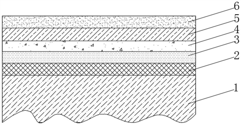
[0057] see Figure 1~5 As shown, the construction method of the steel structure of the main bridge in this embodiment includes the steel structure bridge 1, the epoxy asphalt carbon fiber protective layer 2, the epoxy asphalt macadam shear layer 3, the epoxy asphalt Concrete layer 4, modified epoxy waterproof reinforcement layer 5 and modified epoxy gravel micro-surface treatment layer 6;

[0058] The epoxy asphalt carbon fiber protective layer 2 is composed of a first epoxy asphalt resin layer 21 arranged on the bridge surface of the steel structure bridge 1 and a carbon fiber cloth layer 22 bonded to the first epoxy asphalt resin layer 21;

[0059] The epoxy asphalt macadam shear layer 3 is composed of a second epoxy asphalt resin layer 31 arranged on the carbon fiber cloth layer 22 and a macadam shear layer 32 laid on the second epoxy asphalt resin layer 31;

[0060] The epoxy asphalt concrete layer 4 is formed by solidifying the mixture composed of epoxy asphalt resin, co...

Embodiment 2

[0073] see Figure 6-15 As shown, the bridge deck construction equipment in Embodiment 1 includes an asphalt laying mechanism 100 and an asphalt flat pressing mechanism 200, and the bottom of the asphalt laying mechanism 100 is equipped with an asphalt flat pressing mechanism 200;

[0074] Wherein, the asphalt paving mechanism 100 includes a mounting frame 101, a feeding pipe 102, an outer casing 103, a hopper 105, a support frame 107, a rotating cylinder 109, a driving motor 112, a track 113, a spindle-shaped tank body 118, and conveying and shearing leaves. 120. Auxiliary roller 123, rotating wheels 108 are installed on both sides of the bottom of the mounting frame 101 through the rotating shaft, two supporting frames 107 are installed on the top of the mounting frame 101, and a rotating cylinder is installed on the top of the two supporting frames 107 109, an outer casing 103 is arranged directly above the rotating cylinder 109, a shield cover 104 is installed at one end o...


PUM

PropertyMeasurementUnit
Roughnessaaaaaaaaaa
Thicknessaaaaaaaaaa

Abstract

The invention discloses a main bridge steel structure construction method which comprises the following steps: sequentially paving an epoxy asphalt carbon fiber protective layer, an epoxy asphalt macadam shear layer, an epoxy asphalt concrete layer, a modified epoxy waterproof reinforcing layer and a modified epoxy macadam micro-surfacing treatment layer on a steel structure bridge deck to finish the construction of the steel structure bridge deck of a main bridge. The main bridge steel structure construction method is low in construction environment temperature requirement, normal-temperature construction and normal-temperature curing are achieved, construction conditions are easy to achieve, construction is easy and convenient, by laying the six layers of protection structures on the steel structure bridge deck, the steel structure bridge deck is high in fatigue resistance, resistant to high temperature and water damage, waterproof and corrosion-resistant, the service life of a main bridge is prolonged, meanwhile, raw materials of the six-layer protection structure are common, so that later maintenance is convenient, and cost is low; according to the construction method, laying construction is conducted through the bridge deck laying construction equipment, and the bridge deck laying construction equipment is high in automation degree, high in construction efficiency and low in construction cost.

Description

technical field [0001] The invention relates to the field of bridge construction, in particular to a construction method for a steel structure of a main bridge. Background technique [0002] From the point of view of the entire physical structure of the bridge, the approach bridge abutment at both ends is the dividing point between the route and the abutment, and the part where the bridge hole crosses the main obstacle (such as a river) is called the main bridge. The existing bridge adopts steel structure as the main support structure , and it is necessary to construct the deck of the steel structure bridge to increase the physical performance of the bridge. [0003] When the existing bridge deck is being constructed, a large amount of asphalt mixed raw materials are needed, so several large tankers need to be used to transport the asphalt mixed raw materials from the production area of ​​the asphalt mixed raw materials. The cost is high. [0004] Therefore, how to solve t...

Claims


Application Information

Patent Timeline
IPC IPC(8): E01D21/00
Inventor 罗攀金钱华方超鹏周水香袁飞刘瑾黄洁莉
Owner SHANGHAI GREENLAND CONSTR GRP
Learn More