Permanent magnet motor rotor and motor

A permanent magnet motor and rotor technology, which is applied to the rotating parts of the magnetic circuit, the shape/style/structure of the magnetic circuit, etc., can solve the problems of low effective utilization rate of permanent magnets and poor mechanical centrifugal force resistance, so as to improve the magnetic field effect, Improve the ability to resist vibration and ensure the effect of mechanical strength

Pending Publication Date: 2021-04-16
WUXI NEW GREAT POWER ELECTRICAL MACHINE
View PDF0 Cites 0 Cited by
  • Summary
  • Abstract
  • Description
  • Claims
  • Application Information

AI Technical Summary

Problems solved by technology

[0004] The main purpose of the present invention is to design a kind of permanent magnet motor rotor and motor, to solve the problem that the effective utilization rate of the permanent magnet of the permanent magnet motor in the prior art is low and the anti-mechanical centrifugal force difference, the effective utilization rate of the permanent magnet and The magnetic isolation part of the rotor is closely related, and the mechanical centrifugal force of the rotor is mainly related to the linear velocity of the outer surface of the rotor, that is, the rotational speed of the motor.

Method used


Image

  • Permanent magnet motor rotor and motor
  • Permanent magnet motor rotor and motor
  • Permanent magnet motor rotor and motor

Examples


Embodiment Construction

[0023]In order to make the objects, technical solutions, and advantages of the present invention more clear, the technical solutions of the embodiments of the present invention will be described in contemplation in conjunction with the drawings of the embodiments of the present invention. Obviously, the described embodiments are the embodiments of the present invention, not all of the embodiments. All other embodiments obtained by those of ordinary skill in the art are within the scope of the present invention based on the embodiments of the invention described herein.

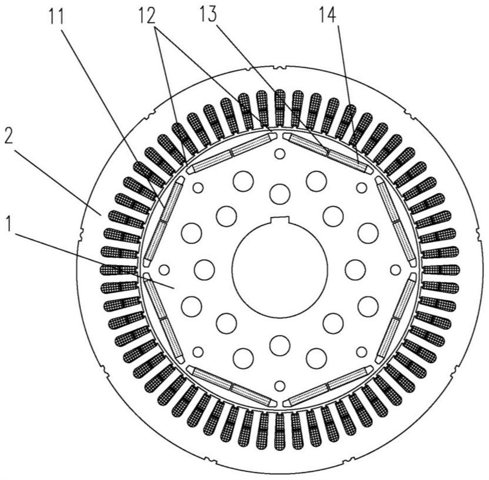
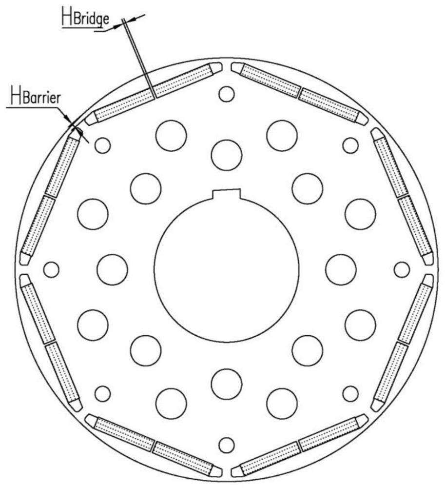
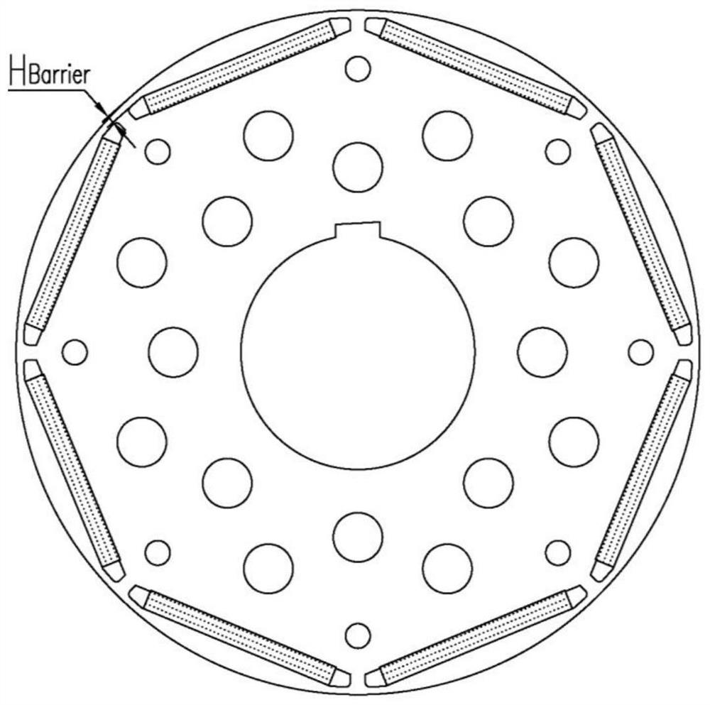
[0024]figure 1 A cross-sectional schematic view of the permanent magnet motor of the present invention is shown schematically. Such asfigure 1 As shown, the permanent magnet motor rotor and motor provided by the present invention include: rotor assembly 1, rectangular groove 11, slight magnetic edge 12, a magnetic bridge 13, a permanent magnet 14, a motor set.

[0025]Such asfigure 1 As shown, the rotor assembly 1 has 2N ...


PUM


Abstract

The invention discloses a permanent magnet motor rotor and a motor. The permanent magnet motor rotor comprises a rotor assembly, 2n (n=1, 2, 3...) built-in rectangular grooves are formed in the rotor assembly along the circumferential surface, the rectangular grooves are linear, magnetic isolation edges are arranged at the two ends of the outer sides of the rectangular grooves, magnetic isolation bridges are arranged at the positions of central symmetry lines of the rectangular grooves, and the number of the magnetic isolation bridges can be set to be zero when the linear speed Vtip of the motor rotor is low, otherwise, the number can be set to be one. According to the linear speed (mechanical centrifugal force of the outer surface of the rotor) of the rotor, the width of the magnetic isolation edges and the number and width of the magnetic isolation bridges are reasonably designed, so that the rotor assembly and the permanent magnets do not move left and right in the rectangular grooves, and the mechanical strength under the centrifugal force is guaranteed; therefore, the magnetic field effect and the output electrical performance of the motor are satisfied, the vibration resistance of the motor rotor is improved, and the rotating speed range of the motor is effectively expanded.

Description

Technical field[0001]The present invention relates to a high-efficiency permanent magnet motor driving device, and in particular, a type load-driven permanent magnet motor rotor and a motor such as a air compressor, a fan and a water pump.Background technique[0002]Permanent magnet motors have been promoted and applied in multiple fields with performance advantages such as efficient, high power density, high volume density, and low temperature rise. Since the rotor magnetic field of the permanent magnet motor is derived from the permanent magnet, the magnetic circuit structure of the rotor is essential to the magnetic flux of the permanent magnet and the mechanical stress ability is critical. It is also one of the key technologies for designing high performance permanent magnet motors, so permanent magnet The rotor magnetic circuit structure of the motor is rational and directly affects the motor operating performance, life and reliability.[0003]At present, the magnetic circuit struc...

Claims


Application Information

Patent Timeline
Patent Type & Authority Applications(China)
IPC IPC(8): H02K1/27
Inventor 徐晓阳王家堡赵卫国黄志杰刘兰刚陈小龙李量
Owner WUXI NEW GREAT POWER ELECTRICAL MACHINE
Why Eureka
Try Eureka