Double-ball-cage electrode catheter device for ablation of tissue in human body cavity

A technology of tissue ablation and electrode catheter, which is applied in the field of medical devices, can solve the problems of short length of annular distributed electrodes, enlarged radial diameter of catheter, and inability to support vessels, so as to ensure overall shape stability, strength and smoothness degree, to ensure the effect of ablation effect

A technology of tissue ablation and electrode catheter, which is applied in the field of medical devices, can solve the problems of short length of annular distributed electrodes, enlarged radial diameter of catheter, and inability to support vessels, so as to ensure overall shape stability, strength and smoothness degree, to ensure the effect of ablation effect

CN112674865APending Publication Date: 2021-04-20HANGZHOUREADY BIOLOGICAL TECH CO LTD

Image

  • Double-ball-cage electrode catheter device for ablation of tissue in human body cavity
  • Double-ball-cage electrode catheter device for ablation of tissue in human body cavity
  • Double-ball-cage electrode catheter device for ablation of tissue in human body cavity

Examples


Embodiment 1

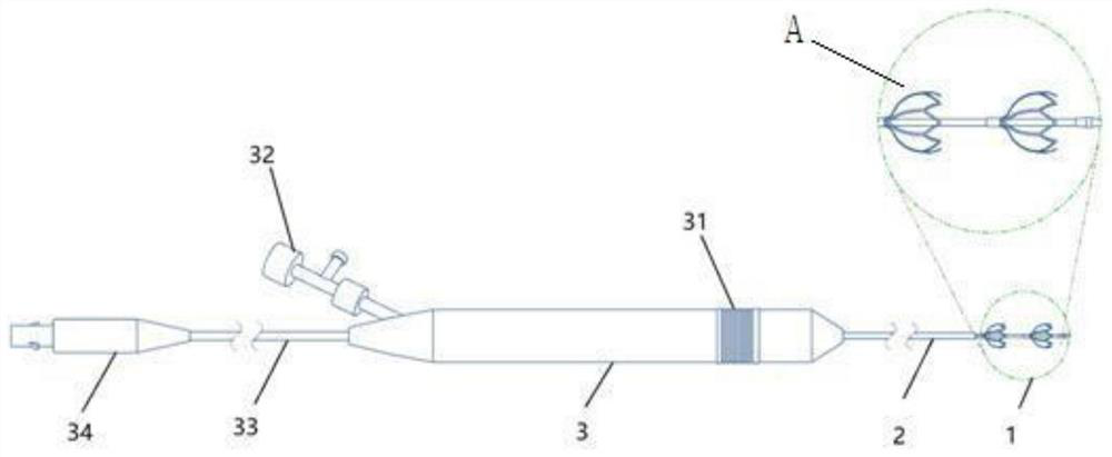
[0051] Embodiment 1: as Figures 1 to 5 As shown, this embodiment describes a double-ball cage electrode catheter device for intraluminal tissue ablation. The specific structure is that the main body of this embodiment is the control handle 3, and the front part of the control handle 3 becomes thinner and extends forward to form the sheath tube 2; The interior of the core tube 21 is hollow to form a wire lumen 24 and a guide wire lumen 25 that are independent of each other. The wire lumen 24 is provided with wires that are connected to the wires 33 and the cage electrodes at both ends, and the guide wire lumen 25 is provided with wires that run through the entire core tube 21. guide wire, the end of the guide wire is set at the tube head 23 at the end of the core tube 21.

[0052] The rear end of the control handle 3 is connected with an electric wire 33 and a plug 34 . A guide wire control unit 32 is also arranged on the control handle 3 , and the other end of the guide wir...

Embodiment 2

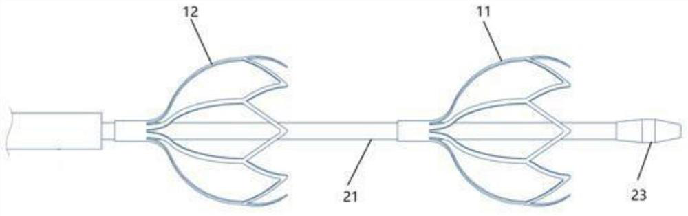
[0063] Such as Figure 7 As shown, this embodiment also describes a double-ball cage electrode catheter device for tissue ablation in a lumen. Its structure is basically the same as Embodiment 1, the difference is that the arc arm branch 112 has two layers. The strength of the two-layer mechanism is easier to control, and the effect of propping up the blood vessels is also better. You can choose to use it according to the actual situation of the lesion.

Embodiment 3

[0065] This embodiment also describes a double-ball cage electrode catheter device for tissue ablation in the cavity. This embodiment is mainly used for the ablation treatment of tumors in the esophagus. Its structure is similar to that of Example 1, because the growth pattern of tumor cells in the esophagus is the same as that of tumor thrombi in the portal vein, both growing along the inner wall of the lumen and gradually growing towards the middle of the lumen. The difference between embodiment 3 and embodiment 1 is that the diameter of the front cage electrode 11 is 3cm; the thickness of the arc arm 111 and the arc arm branch 112 is 1.5cm; the metal pipe diameter of the front cage electrode 11 is 3mm. In this embodiment, the number of arc arms 111 is six.


PUM

PropertyMeasurementUnit
Diameteraaaaaaaaaa
Lengthaaaaaaaaaa
Diameteraaaaaaaaaa

Abstract

The invention relates to a double-ball-cage electrode catheter device for ablation of tissue in a human body cavity. The device comprises a control handle, a tube body, an electric wire, a pulse electrode, a core tube and front and rear ball cage electrodes arranged in pairs, wherein the control handle is matched with a palm of an operator, and the tube body is arranged in the control handle and extends out of a working end of the control handle; the electric wire is arranged in the tube body; the pulse electrode is arranged in the control handle and is used for generating electric pulses for ablating pathological tissues; the core tube is arranged in the tube body, and the core tube freely moves in the tube body in the axial direction; and the front and rear ball cage electrodes are arranged in pairs. The device has the advantages that the structural design is reasonable, the device can effectively aim at a portal vein targeting area, the ablation pertinence is good, the ablation is thorough, and the side effect is small.

Description

technical field [0001] The invention relates to a medical device, which belongs to the field of pulse ablation technology and operation, in particular to a double-ball cage electrode catheter device used for tissue ablation in human cavity. Background technique [0002] In diseases such as cancer and tumor, lesions often occur in disease-related or surrounding cavities. This lesion, different from the tumor itself, often spreads around the wall of the lumen (especially blood vessels), resulting in narrow lumen and spread of diseased tissue. For example, portal vein tumor thrombus (PVTT) is a common complication in the progression of primary liver cancer, which has a special biological behavior of spreading against the portal vein blood flow to the main trunk. The emergence of PVTT will inevitably aggravate portal hypertension, cause a series of symptoms of portal hypertension, affect the quality of life of patients, and threaten the lives of patients. [0003] Radiofrequen...

Claims


Application Information

Patent Timeline
20 Apr 2021
Publication
CN112674865A
IPC
A61B18/12; A61B18/14
Inventors
林晨