Flanging device for container manufacturing

A technology for flanging and container, which is applied to the field of flanging devices for making containers, can solve the problems of high labor intensity, low flanging arc accuracy, low work efficiency, etc., achieves good flanging effect, realizes stepless speed regulation, and improves production. The effect of efficiency

Pending Publication Date: 2021-04-20
黑龙江省建筑安装集团有限公司
View PDF0 Cites 0 Cited by
  • Summary
  • Abstract
  • Description
  • Claims
  • Application Information

AI Technical Summary

Problems solved by technology

[0012] The purpose of the present invention is to provide a device for making flanging of containers, which can replace manual heating and hammering to manufacture the flanging of super large cont

Method used


Image

  • Flanging device for container manufacturing
  • Flanging device for container manufacturing
  • Flanging device for container manufacturing

Examples


Embodiment 1

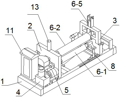
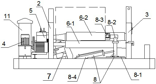
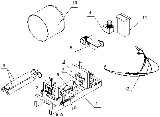
[0057] A flanging device for container production, which consists of: a support system, a rolling system, a push system and a control system, and is characterized in that: the support system consists of a support base 1, a head support frame 2 and a tail support frame 3, the head support frame and the tail support frame are connected with the three work rolls on the rolling system, wherein the head support frame is welded by seamless rectangular steel pipes to form an integral frame, fixed on Just above the transverse support beam at the front end of the supporting base, the supporting frame at the rear is composed of upper and lower structural parts, of which the upper part is a detachable overturning frame, which is welded in the long direction with double channel steel buckles, and can be loaded and unloaded at this position after being laid down Flanged cylinder;

[0058] The rolling system is composed of a motor 4, a reducer 5, three working rolls 6 and a lifting device 1...

Embodiment 2

[0065] According to the container manufacturing flanging device described in Example 1, the support base of the support system is formed by pairing 300*180*8mm seamless rectangular steel pipes, and the described head support frame is formed by 300*180*8mm seamless Seam rectangular steel pipes are welded to form an overall frame, which is a non-detachable part. The lower structure of the tail support frame is a 300*180*8mm seamless rectangular steel pipe fixed directly above the beam of the rear support base, which is a non-detachable part. The joints of the two structures are welded with steel plates and locked with bolts at the front and rear to avoid serial movement when the device is running.

Embodiment 3

[0067] According to the container making flanging device described in embodiment 1 or 2, the outer diameter of the lower roller is 180mm, the diameter of the shaft end is 100mm, and the Y160M-4 three-phase asynchronous motor is connected with the reducer by a V-belt. The first level of speed reduction, the reducer uses the cylindrical output gear and the straight teeth of the two lower rollers to engage with each other to perform the second level of speed reduction, and ensures that the two lower rollers run in the same direction and at the same speed, and the lower roller drives the rollers through electric drive. The outer diameter of the upper roll is 300mm. Since the end of the upper roll is a tapered structure, it can ensure that there is a sufficient distance between the shaft end of the upper roll and the shaft end of the lower roll to meet the space distance required for flanging.


PUM

PropertyMeasurementUnit
Outer circle diameteraaaaaaaaaa
Diameteraaaaaaaaaa
Diameter sizeaaaaaaaaaa

Abstract

The invention relates to a flanging device for container manufacturing. At present, flanging operation is needed when some super-large container workpieces are manufactured, and the workpieces are special in structure, large in appearance size and difficult to machine. The flanging device for container manufacturing comprises a supporting system, a rolling system, a pushing system and a control system, wherein the supporting system is composed of a supporting base (1), a head supporting machine frame (2) and a tail supporting machine frame (3), and three working rollers on the rolling system are connected between the head supporting machine frame and the tail supporting machine frame; and a speed reduction motor (5) is installed on one side of the head supporting machine frame, the speed reduction motor is connected with a motor, the motor (4) and the speed reduction motor are correspondingly installed above a supporting base, and an electric appliance control cabinet (11) in the control system is further installed above the supporting base. The device is applied to the field of machine manufacturing.

Description

technical field [0001] The invention relates to a container making flanging device. Background technique [0002] Container manufacturing is a routine project in the non-standard equipment processing industry. It has formed a mature process and has been applied by many processing companies. However, flanging operations are required when manufacturing super-large container workpieces. For example, some industries (such as medicine and food) will choose a jacketed container with a complete airtight pressure chamber on the outer surface of the ordinary container due to the production process requirements. The workpiece has a special structure and a bulky shape, which makes it difficult to process. [0003] One of the traditional flanging technology construction methods: [0004] Heating pull technology: add arc support at the starting point of the flanging workpiece and temporarily fix it. Oxygen-acetylene flame is evenly distributed on the circumference of the flanged part ...

Claims


Application Information

Patent Timeline
IPC IPC(8): B21D51/26B21D19/04
Inventor 郭兆伟刘艳玲申海洋叶龙张静三徐瀚孙再鑫支猛
Owner 黑龙江省建筑安装集团有限公司
Why Eureka
Try Eureka