Drying room with good drying effect

A drying room and drying technology, which is applied in the direction of preliminary treatment, drying, and drying machine to promote the drying of solid materials, can solve the problems of reduced evaporation effect, labor cost, and increased energy consumption, and achieve the improvement of automatic operation level , improve stability and continuity, and reduce energy loss

Pending Publication Date: 2021-04-20
AMCON FUJIAN ENVIRONMENT PROTECTION EQUIP CO LTD
View PDF5 Cites 0 Cited by
  • Summary
  • Abstract
  • Description
  • Claims
  • Application Information

AI Technical Summary

Problems solved by technology

However, this drying room has the following disadvantages: 1. The hot air with high temperature, low humidity, high wind pressure and high wind speed generated by the heat pump enters the air inlet in the lower position of the drying room.
In the drying room, since the feed inlet is basically on the upper layer, the materials fall down layer by layer until the outlet. Therefore, the materials on the upper layer are in a state of low temperature and high humidity, and cannot obtain high temperature, low humidity, and high wind in time. High-pressure, high-speed hot air, so it cannot heat up and dry quickly
2. The hot air itself has the characteristic of rising upwards. The air entering from the lower layer will make the wind flow upwards faster towards the fixed air duct, resulting in uneven distribution of hot air.
3. The hot air flows upwards from the bottom, so that the more open upper surface of the material cannot get more air flow, and the evaporation effect will be reduced
4. It is difficult to install a dust filter or dust collection device in the drying room. Even if the dust filter or dust collection device is placed in the heat pump room, it is basically necessary to set up a dust filter and dust collection bag and clean it regularly
Not only will it increase wind resistance and consume labor, but also the equipment must be suspended during cleaning, resulting in discontinuous operation of the equipment and increased energy consumption

Method used


Image

  • Drying room with good drying effect
  • Drying room with good drying effect

Examples


Embodiment Construction

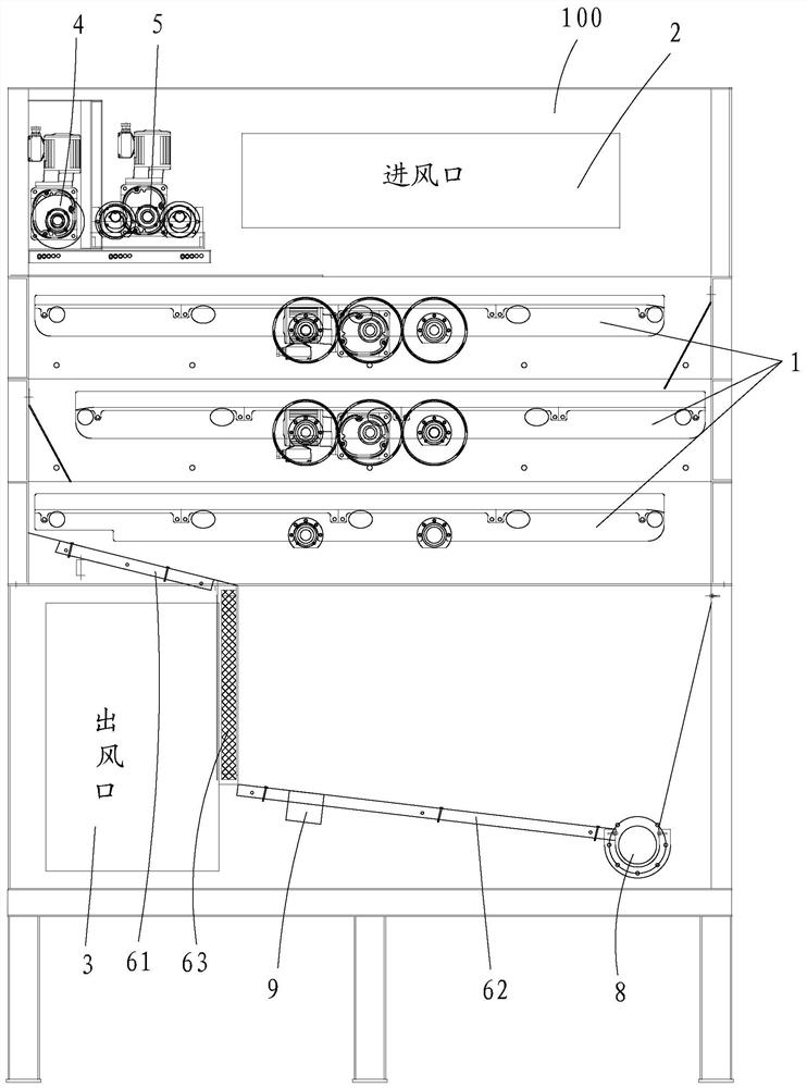
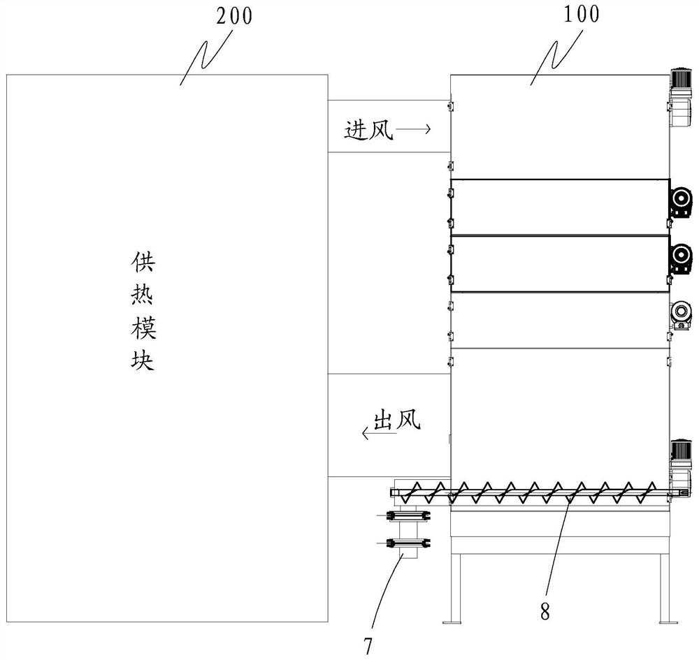
[0025] Such as figure 1 and figure 2 As shown, a drying room 100 with good drying effect is provided with a plurality of material delivery platforms 1 from top to bottom. Air outlet 3 is set below. Both the air inlet 2 and the air outlet 3 are connected to the heating module 200 , and the heating module 200 supplies hot air to the drying room 100 through the air inlet 2 . A blower or an air induction device (not shown) may be provided at the air outlet 3 for guiding the flow of the air and promoting the circulation of the air in the drying room 100 .

[0026] The specific structure of the drying room 100 in this embodiment is a modular drying room. For details, please refer to a drying room disclosed in Chinese invention patent ZL202010175357.9. The difference is that the drying room disclosed in the second embodiment of the specification of this document Each layer of material rolling conveying module in the chamber includes two layers of conveying platforms (each layer o...


PUM


Abstract

The invention discloses a drying room with a good drying effect. A plurality of material conveying platforms are arranged in the drying room from top to bottom, an air inlet is formed in a position above the material conveying platform on the uppermost layer in the drying room, an air outlet is formed in the position below the material conveying platform on the bottommost layer in the drying room, a dustproof material collecting device is arranged in an air outlet area where the air outlet in the drying room is located, the dustproof material collecting device comprises at least two dust collecting inclined plates which are arranged in an inclined mode and a dustproof plate which is connected with the two adjacent dust collecting inclined plates, hot air entering from the air inlet penetrates through the interior of the drying room, reaches the dustproof material collecting device, penetrates through the dustproof plate and then is exhausted from the air outlet, and material slag falling from the material conveying platform in the drying room reaches a discharging device of the drying room through the dustproof material collecting device and is discharged from a discharging port. The drying room not only has a dustproof function, but also more reasonably distributes air quantity and heat, so that materials quickly absorb heat, are dehumidified, dried and hardened.

Description

【Technical field】 [0001] The invention belongs to the technical field of material drying equipment, and specifically refers to a drying room with good drying effect. 【Background technique】 [0002] Material drying equipment is widely used in the drying process of chemical, food, medicine, building materials and other industries. In the field of sludge treatment, the mud cake produced by the sludge dewatering machine falls freely to the mesh crawler belt after granulation or slitting, and is transported by the multi-layer reciprocating mesh belt, and the moisture of the mud cake on the mesh belt gradually increases. Evaporate, and finally form a material with a lower moisture content to discharge. [0003] Chinese invention patent ZL201910748719.6 discloses a peristaltic propulsion type drying equipment, and Chinese invention patent ZL202010175357.9 discloses a material rolling conveying module and its drying chamber. These two kinds of drying rooms use the grid platform to...

Claims


Application Information

Patent Timeline
Patent Type & Authority Applications(China)
IPC IPC(8): F26B1/00F26B15/12F26B21/00F26B25/00F26B25/04
Inventor 郑朝志
Owner AMCON FUJIAN ENVIRONMENT PROTECTION EQUIP CO LTD
Why Eureka
Try Eureka