A method for improving the performance of a depolarizer, a depolarizer, and a mixed-polarization fiber optic gyroscope

A depolarizer, polarization-maintaining fiber technology, applied in Sagnac effect gyroscopes, gyroscopes/steering sensing devices, instruments, etc., can solve the problem that the depolarization effect is not ideal, and the depolarization effect cannot be monitored and improved. and other problems to achieve the effect of improving the depolarization effect, performance improvement, and production efficiency

Active Publication Date: 2022-03-08
HUBEI SANJIANG AEROSPACE HONGFENG CONTROL
View PDF6 Cites 0 Cited by
  • Summary
  • Abstract
  • Description
  • Claims
  • Application Information

AI Technical Summary

Problems solved by technology

In the mixed-polarization fiber optic gyro optical path, since the depolarizer is made of the input optical fiber that comes with the Y waveguide, the two sections of optical fiber are fused at 45° to the axis, and the depolarized optical signal directly enters the Y waveguide for polarization. ° The depolarization effect of the axis cannot be monitored and improved, resulting in unsatisfactory depolarization effect

Method used


Image

  • A method for improving the performance of a depolarizer, a depolarizer, and a mixed-polarization fiber optic gyroscope
  • A method for improving the performance of a depolarizer, a depolarizer, and a mixed-polarization fiber optic gyroscope
  • A method for improving the performance of a depolarizer, a depolarizer, and a mixed-polarization fiber optic gyroscope

Examples


Embodiment Construction

[0025] In order to make the objects, technical solutions and advantages of the present invention, the present invention will be described in detail below with reference to the accompanying drawings and examples. It is to be understood that the specific embodiments described herein are intended to explain the present invention and is not intended to limit the invention. Further, the technical features according to each of the various embodiments described below can be combined with each other as long as they do not constitute a collision between each other.

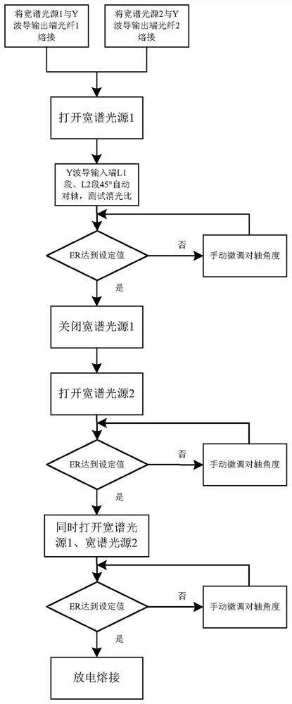
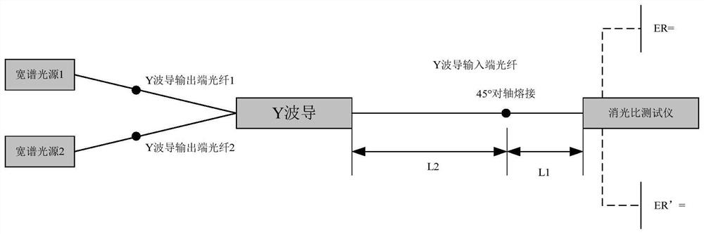
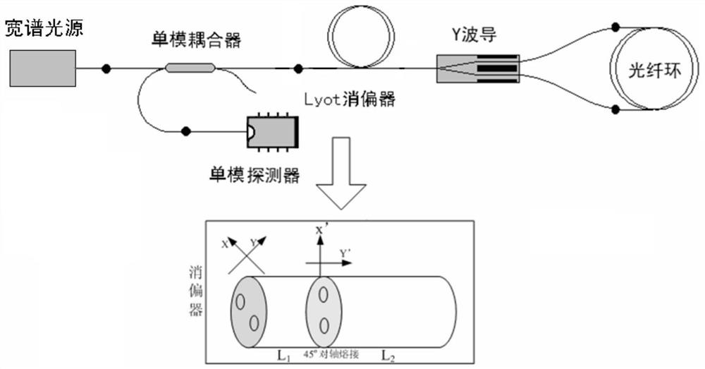
[0026] The working principle of a method of lifting a deficiter performance provided by the present invention will be described in detail below with reference to the examples and the drawings.

[0027] figure 1 It is a schematic diagram of a method of lifting ambulator performance according to an embodiment of the present invention. Such as figure 1 As shown, a method of improving the cleavore performance, the separator inclu...


PUM

PropertyMeasurementUnit
wavelengthaaaaaaaaaa

Abstract

The invention discloses a method for improving the performance of a depolarizer, a depolarizer and a polarization mixing fiber optic gyroscope. The first wide-spectrum light source is welded to the first output end optical fiber of a Y-shaped waveguide, and the second wide-spectrum light source is connected to the first output end optical fiber of a Y-shaped waveguide. The second output fiber of the Y-shaped waveguide is fused, and the extinction ratio tester is connected to the first polarization-maintaining fiber; only the first wide-spectrum light source is turned on, and the 45° alignment between the first polarization-maintaining fiber and the second polarization-maintaining fiber is adjusted. axis angle, so that the first extinction ratio is less than the preset first threshold; only the second broad-spectrum light source is turned on, and the 45° on-axis angle of the first polarization-maintaining fiber and the second polarization-maintaining fiber is adjusted so that the second extinction ratio is less than the preset The second threshold value is set; when the first broadband light source and the second broadband light source are turned on at the same time, when the third extinction ratio is less than the preset third threshold value, the 45° alignment of the first polarization-maintaining fiber and the second polarization-maintaining fiber Discharge welding is carried out at the same point, and the two output ends of the Y waveguide are respectively connected to a wide-spectrum light source for reverse light monitoring, so as to simulate the optical signal transmitted clockwise and counterclockwise in the fiber optic ring of the fiber optic gyroscope, and the improvement of the effect of the depolarizer is more practical. application.

Description

Technical field [0001] The present invention belongs to the field of fiber optic communication technology, and more particularly to a method, a membrane and a mixed polarized fiber gyro. Background technique [0002] Optical fiber gyro is an inertial instrument based on SAGNAC effect, which can measure the rotation angle velocity of relative inertial space. Because there is no moving parts in its composition structure, there is a wide range of applications with small size, light weight, and wide precision coverage, in all areas such as land, sea, empty, and days. The gyro light is a sensitive and detection portion of the SAGNAC effect, which is the core component of the fiber optic gyro. The mixed specification optical path is an optical path form of the fiber optic gyro. In the mixed polarization, a deficitser is added between the single mode fiber coupler and the Y waveguide, the separator uses the Y-waveguide self-contained polarization input tailib, and the input tail is divi...

Claims


Application Information

Patent Timeline
Patent Type & Authority Patents(China)
IPC IPC(8): G01C19/72
CPCG01C19/721
Inventor 郭礼芹路青梅程成康希伦彭志强李亮
Owner HUBEI SANJIANG AEROSPACE HONGFENG CONTROL
Why Eureka
Try Eureka