Phase-sensitive optical time domain reflection device and method based on frequency modulation

A phase-sensitive light and frequency modulation technology, which is applied in the direction of using optical devices to transmit sensing components, measuring devices, and utilizing wave/particle radiation, etc., can solve the problem of increased system complexity, loss of positioning accuracy, and inability to meet the conditions of frequency division multiplexing. and other problems, to achieve the effect of improving the vibration frequency measurement range and vibration size measurement range and improving the response speed.

Active Publication Date: 2021-04-23
GUANGDONG UNIV OF TECH
View PDF10 Cites 5 Cited by
  • Summary
  • Abstract
  • Description
  • Claims
  • Application Information

AI Technical Summary

Problems solved by technology

For example, the optical frequency division multiplexing phase-sensitive optical time domain reflectometer (CN201210124995.3) proposed by Zhou Jun and Cai Haiwen of Shanghai Jiaotong University in 2012 realized the detection of high-frequency vibrations, but it had to increase the pulse width to Avoids spectral aliasing during the measurement, which loses positioning accuracy
In addition, in 2016, the distributed optical fiber sensing system and its vibration detection and positioning method (CN201610719172.3) proposed by He Zuyuan and Liu Qingwen of Shanghai Jiaotong University used sweeping pulses in a coherent structure to achieve multi-channel frequency division multiplexing, although It overcomes the problems of low response bandwidth and positioning accuracy, but its system complexity has also increased a lot
At present, due to the phenomenon of mutual interference in a single pulse and between multiple pulses, the existing chirped pulse and direct detection type -OTDR system can not meet the condition of frequency division multiplexing

Method used


Image

  • Phase-sensitive optical time domain reflection device and method based on frequency modulation
  • Phase-sensitive optical time domain reflection device and method based on frequency modulation
  • Phase-sensitive optical time domain reflection device and method based on frequency modulation

Examples


Embodiment 1

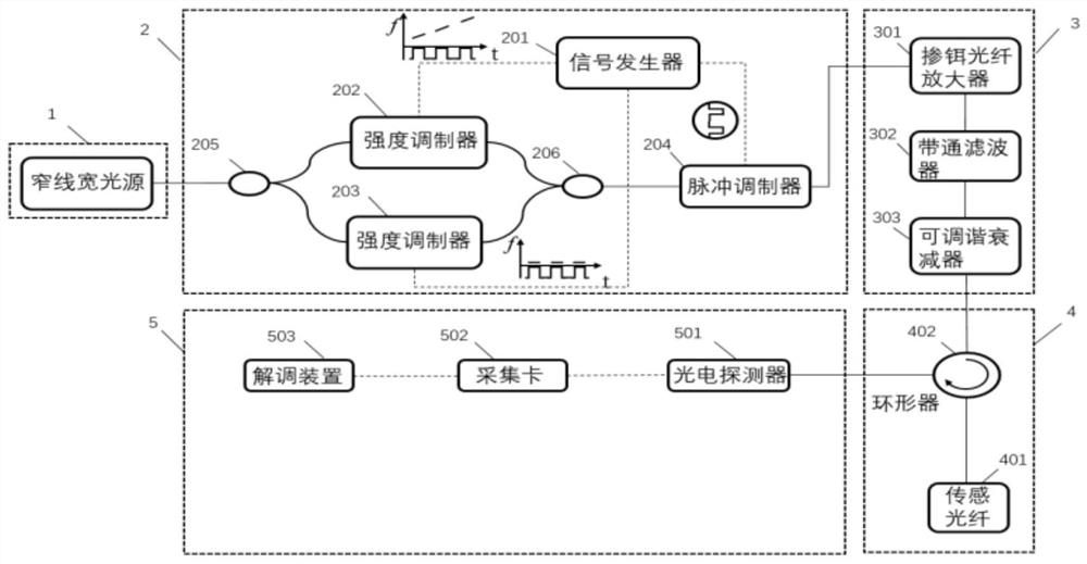
[0078] Such as figure 1 As shown, the present invention provides a phase-sensitive optical time-domain reflection device based on frequency modulation, including a laser light source 1, a frequency modulation device 2, an optical amplification and filtering module 3, a sensing module 4, and a signal acquisition and demodulation device 5; The signal acquisition and demodulation device 5 includes a photodetector 501, an acquisition card 502 and a demodulation device 503; wherein:

[0079] The laser light source 1 emits laser light and is modulated by the frequency modulation device 2 to obtain a multi-frequency pulse signal with a high extinction ratio;

[0080] After the optical amplification and filtering module 3 amplifies the optical power of the multi-frequency pulse signal with high extinction ratio and filters out the noise generated by the amplification, the optical signal is input into the signal acquisition and demodulation device 5 through the sensing module 4 ;

[...

Embodiment 2

[0107] More specifically, on the basis of Embodiment 1, a phase-sensitive optical time-domain reflectometry method based on frequency modulation is provided, including the following steps:

[0108] S1: Modulate the laser to obtain a multi-frequency pulse signal with high extinction ratio;

[0109] S2: Amplify the optical power of the multi-frequency pulse signal with high extinction ratio, filter the noise and transmit it;

[0110] S3: Receive the transmitted optical signal and demodulate the optical signal; by using N non-overlapping digital bandpass filters with different frequency bands, separate the Rayleigh scattering pattern data with non-overlapping frequency bands from the frequency domain, respectively Obtain the Rayleigh scattering patterns of N multi-frequency pulses, and perform cross-correlation between the measured Rayleigh scattering patterns and the Rayleigh scattering reference patterns according to a certain length of window, and the Rayleigh scattering patte...


PUM


Abstract

The invention provides a phase-sensitive optical time domain reflection device and method based on frequency modulation. The method comprises the following steps: dividing laser into two paths, carrying out the synchronous modulation and output of an intensity modulator, obtaining a multi-frequency optical pulse sequence, wherein each optical pulse spectrum is composed of a fixed single frequency and a linear chirp with a non-overlapping frequency band; enabling the sequence to generate backward Rayleigh scattering signals with mutually separated frequency bands in a sensing optical fiber, and obtaining a Rayleigh scattering pattern of each multi-frequency optical pulse by using digital band-pass filters with different frequency bands; and sequentially carrying out related processing on the Rayleigh scattering patterns obtained in sequence, and finally obtaining a disturbance position and a disturbance size thereof. According to the phase-sensitive optical time domain reflection device and method based on frequency modulation provided by the invention, the problem of signal aliasing caused by the fact that a plurality of pulses are hit in a repetition period in a traditional device is solved, the detection interval time is shortened, the measurement speed is greatly improved, and the broadband large-vibration measurement capability of the system is improved.

Description

technical field [0001] The present invention relates to the technical field of optical fiber sensing, and more specifically, to a frequency modulation-based phase-sensitive optical time-domain reflection device and method. Background technique [0002] Phase Sensitive Optical Time Domain Reflectometer - OTDR is a distributed optical fiber sensing technology that enables vibration measurement. When the output light of the laser light source is modulated by the modulator into pulsed light and injected into the sensing fiber, the light is scattered to Rayleigh after being detected by the detector, and the information at the position of the corresponding fiber is obtained according to the time delay of receiving the scattered light. because - OTDR uses a narrow linewidth light source, so what the detector receives is the result of mutual interference and superposition of back Rayleigh scattered light within the pulse width. When the external disturbance acts on the optical ...

Claims


Application Information

Patent Timeline
Patent Type & Authority Applications(China)
IPC IPC(8): G01D5/353G01H9/00
Inventor 杨军叶志耿余鑫峰庄芹芹喻张俊徐鹏柏温坤华王云才秦玉文
Owner GUANGDONG UNIV OF TECH
Why Eureka
Try Eureka