
Heavy oil hydrogenation reactor and hydrogenation method thereof

A technology of heavy oil hydrogenation and hydrogenation reaction, which is applied in chemical instruments and methods, hydroprocessing technology, petroleum industry, etc., and can solve problems such as cracking reaction, insufficient conversion depth, and low mass transfer rate of hydrogen oil

Active Publication Date: 2021-04-27
CHINA PETROLEUM & CHEM CORP +1
View PDF2 Cites 0 Cited by
  • Summary
  • Abstract
  • Description
  • Claims
  • Application Information

AI Technical Summary

Problems solved by technology

However, the following problems still exist in the heavy oil liquid phase hydrogenation reactor and the reaction process: (1) The heavy oil has a high viscosity and the mass transfer rate of the hydrogen oil is low, resulting in a low hydrogenation reaction rate; (2) The catalyst for the heavy oil hydrogenation process is generally Gradation is required, that is, the combination of catalysts with multiple functions and multiple activities is required, but no matter whether you choose low-activity or high-activity catalysts, there are still side reactions on the surface of catalysts with high catalyst activity due to residence time and heat transfer. Or the cracking reaction is serious, which leads to the problem that the catalyst is easy to coke and the liquid yield is low; (3) The hydrogenation process of heavy oil is much more difficult than the hydrogenation process of light oil, especially the impurities such as sulfur, nitrogen, and metals are very high. In the reactor, especially in the early stage of the reaction, the impurity concentration of the reactants is high, the reaction driving force is large, and the reaction is violent, resulting in concentrated heat release and uneven temperature rise. Therefore, it is very important to control the slow contact between the raw material and the catalyst; (4) Based on heavy oil raw materials The impurity content is high, and it is very difficult to achieve deep removal, especially in the later stage of the reaction, the inhibitory effect of gas products on the conversion rate is more obvious
The method of the invention is mainly to improve heat transfer and mass transfer efficiency, ensure sufficient residence time of materials in the reactor, and increase conversion rate of heavy oil and yield of light oil, but only through conventional hydrogenation reactor structure, it is not effective The contact time between the catalyst and the raw material is controlled, and the conversion rate of heavy oil and the yield of light oil cannot be guaranteed.
[0007] To sum up, most of the heavy oil hydrogenation reactors in the prior art are designed to improve the hydrogenation reaction efficiency by improving the process of the existing equipment and increasing the residence time of the material, without solving the problem of the heavy oil liquid phase hydrogenation reaction. The process has problems such as low reaction rate, insufficient conversion depth, uneven temperature rise, low liquid yield caused by long residence time, serious side reactions and cracking reactions, etc.

Method used


Image

  • Heavy oil hydrogenation reactor and hydrogenation method thereof
  • Heavy oil hydrogenation reactor and hydrogenation method thereof
  • Heavy oil hydrogenation reactor and hydrogenation method thereof

Examples


Embodiment 1

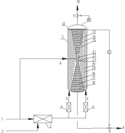
[0042] with attached figure 1 In the described method, the catalyst III filled in the outer cylinder of the heavy oil hydrogenation reactor adopts the FZC protective agent / FF-46 catalyst developed by the Fushun Petrochemical Research Institute, wherein the FZC protective agent is 15% of the total catalyst volume of the outer cylinder, and the inner cylinder is 15% of the total catalyst volume. The catalyst I packed in I adopts the 3936 catalyst developed by the Fushun Petrochemical Research Institute, and the catalyst II packed in the inner cylinder II adopts the 3996 catalyst developed by the Fushun Petrochemical Research Institute.

[0043] The hydrogen contained in the feed of the heavy oil hydrotreating reactor is 8.66% of the mass of the raw oil (the sum of the fresh raw oil and the circulating oil); oil sum) 3.28% of the mass; the circulation ratio is 2.5.

[0044] The reaction conditions of the outer cylinder of the hydrogenation reactor are as follows: the reaction te...

Embodiment 2

[0048] with attached figure 1 In the described method, the catalyst III filled in the outer cylinder of the heavy oil hydrogenation reactor adopts the FZC protective agent / FF-46 catalyst developed by the Fushun Petrochemical Research Institute, wherein the FZC protective agent is 15% of the total catalyst volume of the outer cylinder, and the inner cylinder is 15% of the total catalyst volume. The catalyst I packed in I adopts the 3996 catalyst developed by the Fushun Petrochemical Research Institute, and the catalyst II packed in the inner cylinder II adopts the FF-26 catalyst developed by the Fushun Petrochemical Research Institute.

[0049] The hydrogen contained in the feed of the heavy oil hydrogenation reactor is 9.66% of the mass of the raw oil (the sum of the fresh raw oil and the circulating oil); oil sum) 2.75% of the mass; the circulation ratio is 2.8.

[0050]The reaction conditions of the outer cylinder of the hydrogenation reactor are as follows: the reaction te...

Embodiment 3

[0054] with attached figure 1 In the described method, the catalyst III filled in the outer cylinder of the heavy oil hydrogenation reactor adopts the FZC protective agent / FF-46 catalyst developed by the Fushun Petrochemical Research Institute, wherein the FZC protective agent is 15% of the total catalyst volume of the outer cylinder, and the inner cylinder is 15% of the total catalyst volume. The catalyst I packed in I adopts the 3996 catalyst developed by Fushun Petrochemical Research Institute, and the catalyst II packed in the inner cylinder II adopts the TK-555 catalyst developed by Topsoe Company.

[0055] The hydrogen contained in the feed of the heavy oil hydrogenation reactor is 8.80% of the mass of the raw material oil (the sum of the fresh raw material oil and the circulating oil). oil sum) 3.15% of the mass; the circulation ratio is 2.5.

[0056] The reaction conditions of the outer cylinder of the hydrogenation reactor are as follows: the reaction temperature is ...


PUM


Abstract

The invention discloses a heavy oil hydrogenation reactor and a hydrogenation method. The reactor comprises an outer cylinder, an inner cylinder I, a hydrogen supplementing assembly and an inner cylinder II, the inner cylinder I, the hydrogen supplementing assembly and the inner cylinder II are arranged in the axial direction of the reactor, and an annular cavity is formed between the inner cylinder and the outer cylinder; wherein the inner cylinder I is filled with a hydrogenation catalyst I, the inner cylinder II is filled with a hydrogenation catalyst II, the annular cavity is filled with a hydrogenation catalyst III, and the catalyst activity is as follows: the hydrogenation catalyst III is greater than the hydrogenation catalyst II, and the hydrogenation catalyst II is greater than the hydrogenation catalyst I; the hydrogen supplementing assembly is a shell-and-tube ceramic membrane tube, the side of the ceramic membrane tube is communicated with a hydrogen pipeline, and a cavity outside the tube is respectively communicated with the bottom of the inner cylinder I and the top of the inner cylinder II. The outer cylinder, the inner cylinder I, the hydrogen supplementing assembly and the inner cylinder II are arranged in the reactor, so that after the viscosity of reaction feed is reduced, the reaction feed sequentially passes through the outer cylinder, the inner cylinder I, the hydrogen supplementing assembly and the inner cylinder II to generate hydrogenation reaction, the mass transfer driving force and reaction rate in the heavy oil liquid phase hydrogenation reaction process are improved, catalyst surface coking is relieved, and side reaction and cracking reaction are reduced.

Description

technical field [0001] The invention belongs to the field of petrochemical industry, and in particular relates to a heavy oil hydrogenation reactor and a hydrogenation method. Background technique [0002] With the hydrogenation of crude oil becoming heavier and inferior, the proportion of heavy crude oil and secondary processed oil is getting higher and higher. Therefore, heavy oil hydroprocessing technology has become one of the hot spots in the research of hydrogenation process. Heavy oil hydrogenation reactors are divided into various types, such as fixed bed hydrogenation reactors, suspension bed hydrogenation reactors, ebullating bed type of heavy oil. [0003] In the heavy oil hydrogenation process, compared with the traditional fixed-bed gas / liquid / solid three-phase hydrogenation process, the liquid-phase hydrogenation process has the advantages of fast hydrogenation reaction rate, high reaction efficiency, high catalyst utilization rate, and energy efficiency. It ...

Claims


Application Information

Patent Timeline
IPC IPC(8): B01J8/04C10G67/00
CPCB01J8/04B01J8/0492B01J8/0496C10G67/00B01J2208/025C10G2300/4006C10G2300/4012C10G2300/4018
Inventor 高峰杨秀娜何佳阮宗琳
Owner CHINA PETROLEUM & CHEM CORP
Learn More