
Method for high-speed laser cladding of Mo-Cu alloy layer on copper substrate

A technology of laser cladding and alloy layer, applied in metal material coating process, coating and other directions, can solve problems such as low mutual solubility, finished product strength, electrical conductivity and performance uniformity can not meet the requirements, cumbersome process and so on

Pending Publication Date: 2021-04-27
ZHEJIANG UNIV
View PDF5 Cites 2 Cited by
  • Summary
  • Abstract
  • Description
  • Claims
  • Application Information

AI Technical Summary

Problems solved by technology

[0004] Using Mo-Cu alloy powder to clad Mo-Cu alloy on the surface of copper alloy can effectively save costs, but the current method of preparing Mo-Cu alloy powder usually has poor material uniformity, many closed voids, and The density is usually lower than 98%, or the process is cumbersome, the production efficiency is low, it is difficult to produce in batches, and the production cost is high.
In addition, Mo-Cu mixed powder can be used to process the surface of parts. This method has wide sources of powder, low cost and easy operation. However, due to the large quality difference between Mo and Cu and low mutual solubility, it is easy to process Mo-Cu. The agglomeration and delamination of Mo and Cu occur when the powder is mixed, which leads to the failure of the strength, electrical conductivity and performance uniformity of the finished product obtained in the subsequent processing.

Method used


Image

  • Method for high-speed laser cladding of Mo-Cu alloy layer on copper substrate
  • Method for high-speed laser cladding of Mo-Cu alloy layer on copper substrate
  • Method for high-speed laser cladding of Mo-Cu alloy layer on copper substrate

Examples


Embodiment 1

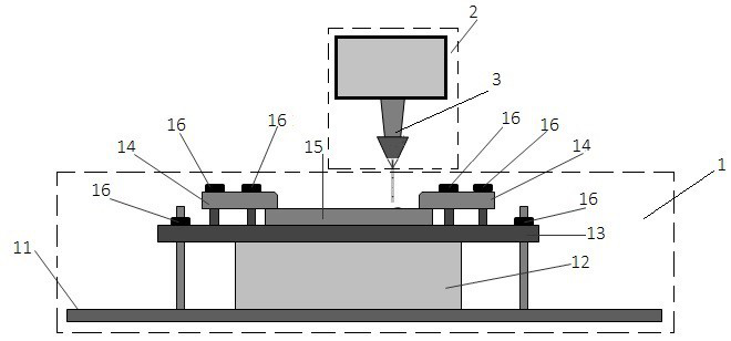
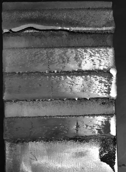
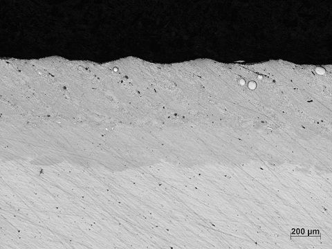
[0041] Prepare a copper plate with a size of 6mm×150mm×100mm, grind and clean it until the surface is smooth and clean, the cladding powder is 300 mesh Mo powder and Cu powder, use a platform-type high-frequency vibration platform to apply high-frequency vibration, and perform double-tube layered gradient cladding The specific parameters are the first layer: Mo powder feeder speed 0.2rpm, Cu powder feeder speed 0.3rpm, power 3500W, cladding distance 15.5mm, protective gas (argon) 14L / min, cladding head moving speed 0.05mm / s, preheating temperature 200°C. The second layer: Mo powder feeder speed 0.3rpm, Cu powder feeder speed 0.4rpm, power 3300W, cladding distance 15.5mm, protective gas (argon) 14L / min, cladding head moving speed 0.05mm / s, preheating temperature 200°C. The third layer: Mo powder feeder speed 0.4rpm, Cu powder feeder speed 0.4rpm, power 3000W, cladding distance 15.5mm, protective gas (argon) 14L / min, cladding head moving speed 0.05mm / s, preheating temperatur...


PUM

PropertyMeasurementUnit
particle sizeaaaaaaaaaa
thicknessaaaaaaaaaa
lengthaaaaaaaaaa

Abstract

The invention discloses a method for laser cladding of a Mo-Cu alloy layer on a copper substrate. The method comprises the following steps: 1) drying Mo powder and Cu powder in vacuum; 2) polishing and cleaning a cladding substrate; (3) performing cladding with a high-speed laser cladding device, during cladding, adopting double-cylinder powder feeding, and controlling the powder feeding amount of the Mo powder and Cu powder respectively to achieve the purpose of gradient cladding, wherein the mass ratio of Mo to Cu of the cladding alloy layer is sequentially increased in a gradient mode, in addition, the cladding substrate is loaded on a high-frequency vibration platform, and the high-frequency vibration platform generates platform type vibration during cladding. Gradient cladding is adopted, the binding force between a cladding layer and a base body and the strength of the cladding layer are improved, and the uniformity of Mo and Cu components and structures in the cladding layer is improved through double-cylinder powder feeding. High-frequency vibration in cladding effectively releases thermal stress in the cladding layer, improves the strength of the cladding layer, improves the fluidity of a molten pool, reduces air hole shrinkage in the cladding layer, improves the strength of the cladding layer and the like.

Description

technical field [0001] The invention relates to a high-speed laser cladding technology, in particular to a method for a high-speed laser cladding alloy layer on a copper substrate. Background technique [0002] High-speed laser cladding is a technical method widely used in surface modification of metal materials, which can effectively improve the surface properties of metal substrates and increase the service life of metal materials. Copper alloys are widely used in electronics, electrical, machinery manufacturing and other process sectors because of their good electrical and thermal conductivity. However, with the continuous development of various industries, the performance of traditional copper alloys can no longer meet the needs of some special working environments. Therefore, it is necessary to use laser cladding as a surface modification method to further improve the performance of copper alloys. [0003] Combining the advantages of Cu and Mo, Mo-Cu alloy has many adv...

Claims


Application Information

Patent Timeline
Patent Type & Authority Applications(China)
IPC IPC(8): C23C24/10
CPCC23C24/106
Inventor 王宏涛刘嘉斌寿建栋谢宏斌高铭余方攸同
Owner ZHEJIANG UNIV
Learn More