Industrial solid waste treatment system

A solid waste, treatment system technology, applied in the direction of combustion method, lighting and heating equipment, combustion type, etc., can solve the problems of damage, high temperature of motor, etc.

Pending Publication Date: 2021-04-27
史川徽
View PDF5 Cites 0 Cited by
  • Summary
  • Abstract
  • Description
  • Claims
  • Application Information

AI Technical Summary

Problems solved by technology

At present, the waste slag produced after incineration of industrial solid waste is often discharged by using the slag discharge barrel with the screw conveying blade, but the screw conveying blade is directly connected with the output end of the motor that drives its rotation, and then the waste slag with higher temperature falls into the After entering the slag discharge barrel, the heat is transferred to the motor through heat transfer, which makes the motor temperature higher and damaged

Method used


Image

  • Industrial solid waste treatment system
  • Industrial solid waste treatment system
  • Industrial solid waste treatment system

Examples


specific Embodiment approach

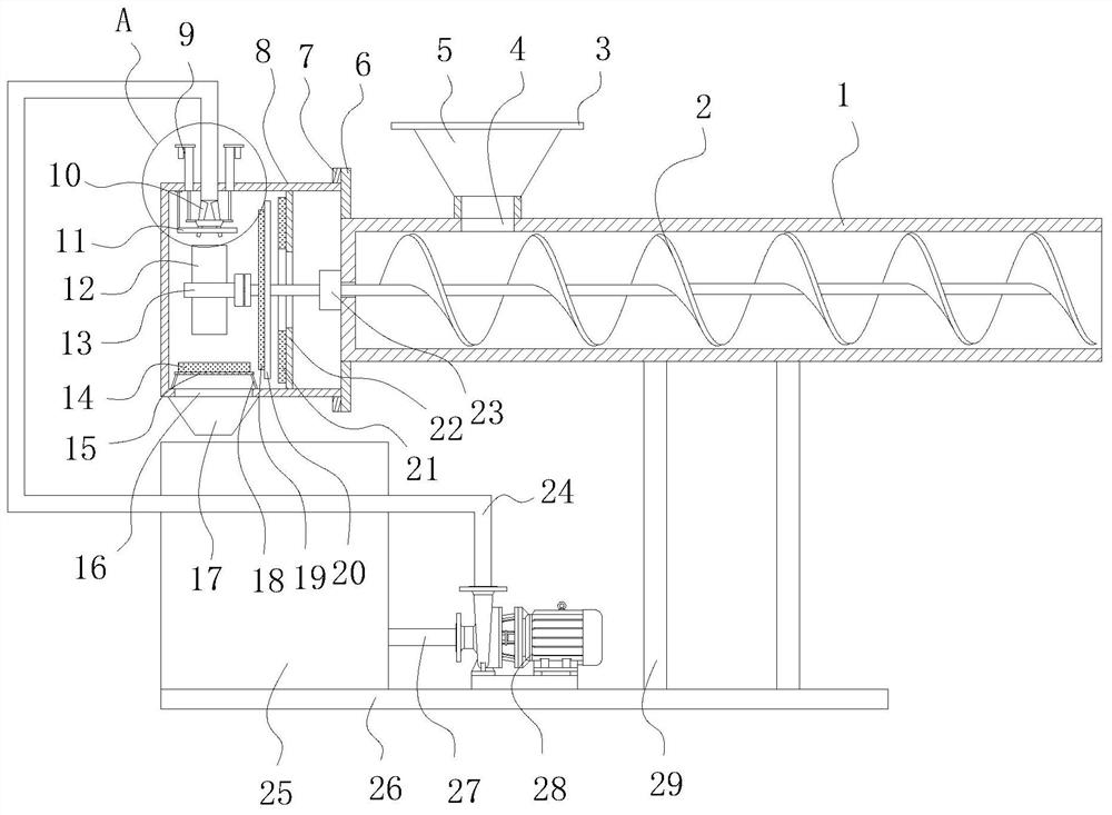
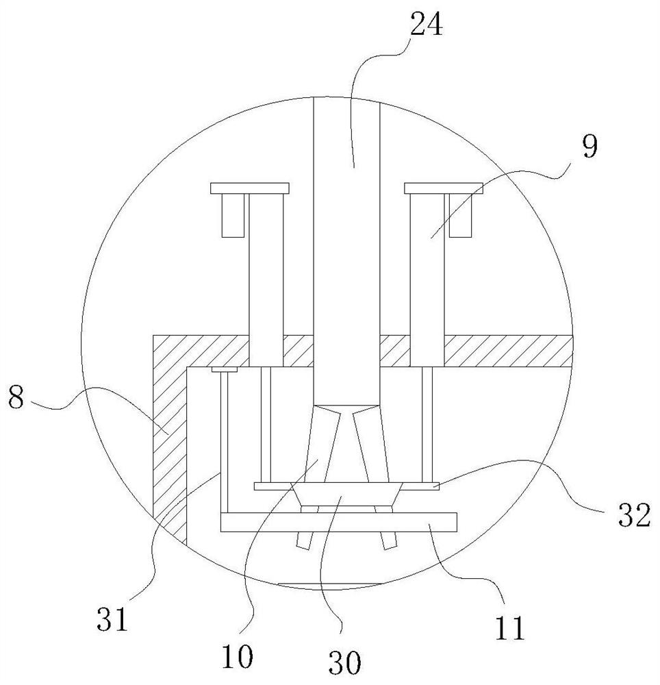
[0039] Specific implementation method: After connecting the circuit of the high-pressure water pump 28, the high-pressure water pump 28 pumps the water in the water storage tank 25 to the water delivery pipe 24, and then the water in the water delivery pipe 24 impacts on the water-retaining blade 12 at a high speed, thereby retaining the water The blade 12 drives the transmission rod 13 to rotate, and the transmission rod 13 drives the screw conveying blade 2 to rotate in the slag discharge barrel 1, and then the waste slag falling into the slag discharge is discharged under the push of the screw conveying blade 2, realizing the use of high-pressure water impact to drive the screw conveying The purpose of the rotation of the blade 2 is to prevent the heat from damaging the driving equipment. The water flowing into the cylinder 8 flows into the water leakage funnel 17 through the water outlet 16, and then the water is collected by the water leakage funnel 17 into the water storag...


PUM


Abstract

The invention relates to the technical field of solid waste incineration, in particular to an industrial solid waste treatment system which comprises a slag discharging cylinder and a spiral conveying blade rotationally installed in the slag discharging cylinder, a detachable cylinder is installed at one end of the slag discharging cylinder, and a detachable transmission rod is installed at the end, located in the cylinder, of the spiral conveying blade. A plurality of water retaining blades are annularly mounted on the outer surface of the transmission rod at equal intervals, a water conveying pipe facing the water retaining blades is mounted at the upper portion of the outer surface of the cylinder, and the end, away from the cylinder, of the water conveying pipe is connected with a high-pressure water pump water outlet end which is connected with a water storage tank through a connecting pipe. A water flow rate control assembly is mounted at the end, in the cylinder, of the water conveying pipe. Compared with the prior art, the industrial solid waste treatment system has the following beneficial effects that the purpose of driving the spiral conveying blade to rotate through high-pressure water impact is achieved, and heat is prevented from damaging driving equipment.

Description

technical field [0001] The invention is an industrial solid waste treatment system, which belongs to the technical field of solid waste incineration. Background technique [0002] Industrial solid waste is burned at high temperature in special equipment to convert combustible waste into simple inorganic substances such as carbon dioxide and water. The weight reduction rate after incineration is generally greater than 70%, and the volume reduction rate is greater than 80%, which can greatly reduce the amount of waste and at the same time completely kill various pathogens. At present, the waste slag produced after incineration of industrial solid waste is often discharged by using the slag discharge barrel with the screw conveying blade, but the screw conveying blade is directly connected with the output end of the motor that drives its rotation, and then the waste slag with higher temperature falls into the After entering the slag discharge barrel, the heat is transferred to...

Claims


Application Information

Patent Timeline
IPC IPC(8): F23G5/44F23J1/06F03B13/00
CPCF23G5/44F23J1/06F03B13/00F23J2700/003
Inventor 史川徽
Owner 史川徽
Why Eureka
Try Eureka