Air cooling structure and pressure cooker
A technology of air-cooled structure and pressure cooker, which is applied in pressure cooker, household refrigeration device, lighting and heating equipment, etc. It can solve the problem of long natural cooling time of pressure cooker, increase heat dissipation effect, disperse air inlet area, and improve cooling efficiency Effect
- Summary
- Abstract
- Description
- Claims
- Application Information
AI Technical Summary
Problems solved by technology
Method used
Image

Examples
Embodiment 1
[0069]CombineFigure 1 - Figure 14 As shown, the air-cooled structure provided in this embodiment includes:
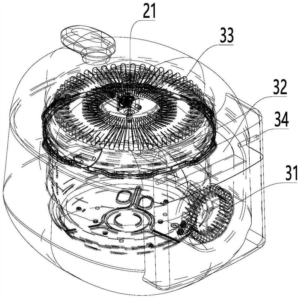
[0070]Availability 32;
[0071]The fan 31 is disposed at the first end of the air passage 32;
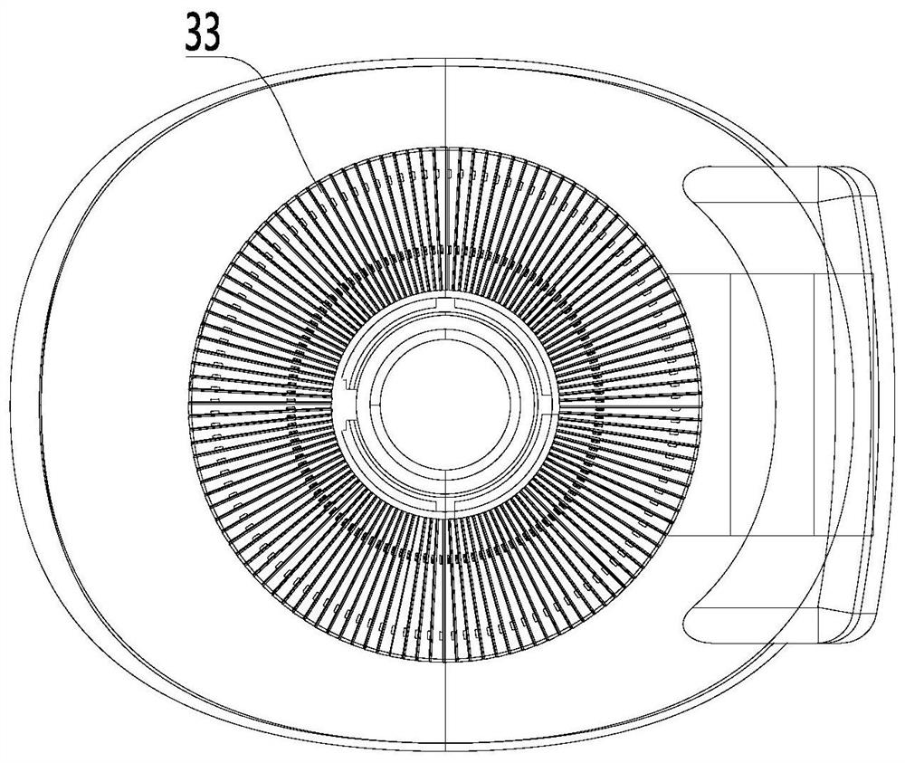
[0072]The heat sink assembly 33 is disposed at the second end of the airway 32 and communicates with the fan 31 via the wind channel 32, and the heat sink assembly 33 is adapted to contact with the heat dissipation structure;
[0073]The first end of the air passage 32 is also provided with the second end, and the air outlet 323 and the air opening 21 are provided, and the second end of the air passage 32 is provided with a wind port 21 or the air outlet 323;
[0074]The heat sink assembly 33 is performed in the edge of the winding end 331 or the wind end 332, and the central portion of the heat sink assembly 33 is formed with a wind end 332 or a winding end 331, and the air end 331 and the The wind terminal 332 is connected by a heat dissipation channel.
[0075]The air-cooling structure provided i...
Embodiment 2
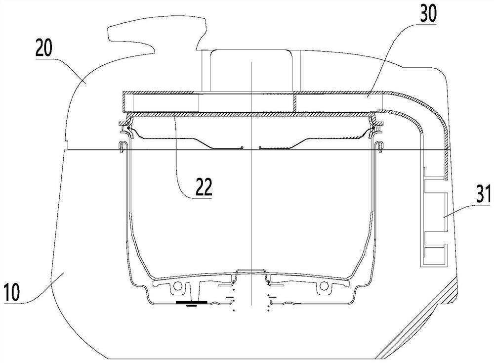
[0109]CombineFigure 1 - Figure 3 As shown, this embodiment provides a pressure 煲, including:
[0110]Body 10;
[0111]Covered cover 20, the hockey cover 20 is attached to the hinge body 10 by the hinge shaft 34; and
[0112]The air cooling structure as described above is described above.
[0113]The pressure 煲 provided in this embodiment is by using the air-cooling structure, solve the pressure cooker fast cooling and relief opening problem, enhance the user experience, and can reduce the opening time by rapid pressure, reduce the opening time, reducing the actual pressure of food, and the cooking time is long. The situation, shorten the gap between the actual cooking time and the setting cooking time, and further guarantee the consistency of the cooking mouth, avoid affecting the taste.
[0114]Preferably, the air-cooling structure is provided on the pressure cooker, which can quickly relieve the pressure, reduce the environmental contamination or even burns of the user who may be self-reliant.
[0...
Embodiment 3
[0130]CombineFigure 8 - Figure 13As shown, the heat sink provided in this embodiment includes:
[0131]Base plate 45;
[0132]The support rib 41 is extended from the surface of the bottom plate 45 toward the direction away from the bottom plate 45;
[0133]The first fitting member 42 and the second fitting fitting 43, the first fitting member 42 or the second fitting fitting 43 is adapted to the second assembly 43 or the first assembly 42 on the side of the sink adjacent to another. Take the card connection.
[0134]The heat sink is achieved by assembling the first fitting member 42 and the second fitting fitting 43 on the heat sink, and the adjacent two sink can be assembled by the first fitting fitting 42 and the second assembly 43. The combination is convenient for manufacturing the heat sink using a mass production form, and is assembled, and the structural form of a plurality of the heat sinks is exactly the same, and there is no need to find a suitable assembly in the assembly, speed asse...
PUM
 Abstract
Description
Claims
Application Information
 - R&D
- Intellectual Property
- Life Sciences
- Materials
- Tech Scout
- Unparalleled Data Quality
- Higher Quality Content
- 60% Fewer Hallucinations
Browse by: Latest US Patents, China's latest patents, Technical Efficacy Thesaurus, Application Domain, Technology Topic, Popular Technical Reports.
© 2025 PatSnap. All rights reserved.Legal|Privacy policy|Modern Slavery Act Transparency Statement|Sitemap|About US| Contact US: help@patsnap.com