Supercharge Your Innovation With Domain-Expert AI Agents!

Laser cutting process used for oil tank blanking

A laser cutting and fuel tank technology, applied in laser welding equipment, applications, household containers, etc., can solve the problems of inability to ensure smooth sections and violent reactions, and achieve the effect of ensuring consistency, uniform temperature and increasing heat.

Active Publication Date: 2021-04-30
无锡市祁丰钣金有限公司
View PDF4 Cites 2 Cited by
  • Summary
  • Abstract
  • Description
  • Claims
  • Application Information

AI Technical Summary

Problems solved by technology

[0004] Aiming at the deficiencies of the existing technology, the invention discloses a laser cutting process for fuel tank blanking, in order to solve the problems in the prior art that oxygen participates in the combustion during the laser cutting process, which makes the high temperature lead to a violent reaction and cannot ensure a smooth cross section.

Method used


Image

  • Laser cutting process used for oil tank blanking
  • Laser cutting process used for oil tank blanking
  • Laser cutting process used for oil tank blanking

Examples


no. 1 example

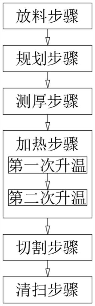
[0072] Include the following steps:

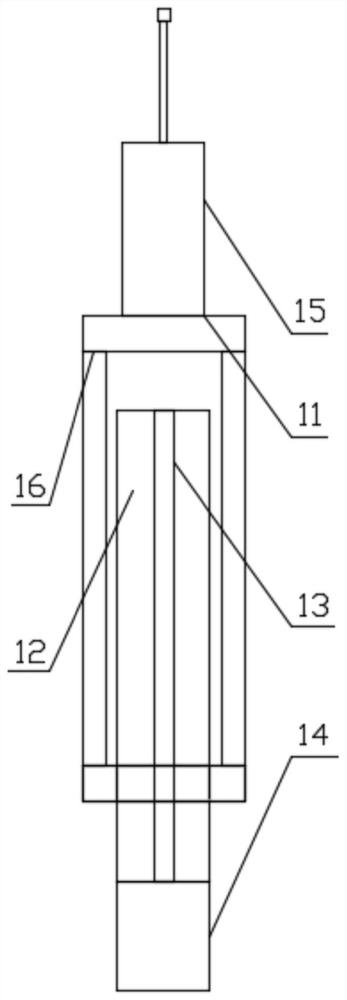
[0073] The discharging step: placing the raw material on the cutting table; a plurality of first measuring devices 11 are arranged side by side on the cutting table; the first measuring device 11 is used to measure the height of the lower surface of the raw material;

[0074] Planning steps; use the camera mechanism to photograph the upper surface of the raw material; calculate the laser cutting path according to the photographed picture;

[0075] Thickness measuring step: using the second measuring mechanism to measure the height of the upper surface of the raw material; the second measuring mechanism moves along the laser cutting path; obtaining the thickness of multiple positions of the raw material laser cutting path. The raw material thickness is 3.95mm, 3.97mm, 4.02mm, 4.05mm in turn.

[0076] A heating step is also included between the thickness measuring step and the cutting step; the heating step specifically includes;

[0077] ...

no. 2 example

[0083] Include the following steps:

[0084]Feeding step. Place ingredients on cutting table. Several first measuring devices 11 are arranged side by side on the cutting table. The first measuring device 11 is used for measuring the height of the lower surface of the raw material.

[0085] Planning steps. The upper surface of the raw material is photographed by a camera mechanism. Calculate the laser cutting path based on the photographed image.

[0086] Thickness measurement step. Use the second measuring mechanism to measure the height of the upper surface of the raw material. The second measuring mechanism moves along the laser cutting path. Obtain the thickness of multiple positions in the raw material laser cutting path. The range of raw material thickness is 3.95mm, 4.01mm, 3.96mm, 4.04mm.

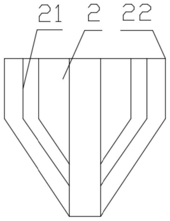
[0087] Cutting step. Use the cutter 2 to emit laser light to cut the raw material. The power of cutter 2 is 3000W, 3600W, 3100W, 3900W. A first nozzle 21 is arranged arou...

no. 3 example

[0091] Include the following steps:

[0092] Feeding step. Place ingredients on cutting table. Several first measuring devices 11 are arranged side by side on the cutting table. The first measuring device 11 is used for measuring the height of the lower surface of the raw material.

[0093] Planning steps. The upper surface of the raw material is photographed by a camera mechanism. Calculate the laser cutting path based on the photographed image.

[0094] Thickness measurement step. Use the second measuring mechanism to measure the height of the upper surface of the raw material. The second measuring mechanism moves along the laser cutting path. Obtain the thickness of multiple positions in the raw material laser cutting path. The raw material thickness range is 3.97mm, 4.04mm, 4.05mm, 3.96mm.

[0095] A heating step is also included between the thickness measuring step and the cutting step; the heating step specifically includes;

[0096] The first heating up; heati...


PUM

PropertyMeasurementUnit
thicknessaaaaaaaaaa

Abstract

The invention relates to a laser cutting process used for oil tank blanking. The laser cutting process is characterized by comprising the following steps that a material putting step is carried out, specifically, a raw material is put on a cutting table, and a first measuring device is used for measuring the lower surface height of the raw material; a planning step is carried out, specifically, the upper surface of the raw material is shot by a camera mechanism, and a laser cutting path is calculated according to the shot image; a thickness measuring step is carried out, specifically, the upper surface height of the raw material is measured by adopting a second measuring mechanism; the second measuring mechanism moves along the laser cutting path, and the thickness of the laser cutting path of the raw material is obtained; a cutting step is carried out, specifically, a cutter is adopted to emit laser to cut the raw material, a first nozzle is arranged around the cutter, the first nozzle sprays combustion-supporting gas, second nozzles surround the first nozzle, and the second nozzles spray inert gas; and a cleaning step is carried out, specifically, slag is purged by adopting a purging mechanism; and the purging mechanism moves along the laser cutting path. The problems, caused by an existing scheme, that in the laser cutting process, oxygen participates in combustion, reaction is violent due to high temperature, and smooth sections cannot be guaranteed are solved.

Description

technical field [0001] The invention relates to a cutting process, in particular to a laser cutting process for fuel tank blanking. Background technique [0002] Generally, the laser beam is irradiated on the surface of the material through the nozzle, and the material reaches a molten state after absorbing energy, and the auxiliary gas blows away the molten liquid material, and the melting point area gradually moves with the cutting direction to form a continuous slit, which is laser cutting. . The material to be cut is irradiated with a high-power-density laser beam, so that the material is quickly heated to the vaporization temperature, and evaporates to form holes. As the beam moves to the material, the holes continuously form narrow slits to complete the cutting of the material. Oxygen is used to assist cutting in the laser cutting process, but the existing solutions lead to rough cut sections, and how to solve this problem becomes crucial. [0003] In the existing sc...

Claims


Application Information

Patent Timeline
Patent Type & Authority Applications(China)
IPC IPC(8): B23K26/38B23K26/14B23K26/03B23K26/60B23K26/142
CPCB23K26/38B23K26/14B23K26/032B23K26/60B23K26/142B23K2101/12
Inventor 高宇超
Owner 无锡市祁丰钣金有限公司
Features
  • R&D
  • Intellectual Property
  • Life Sciences
  • Materials
  • Tech Scout
  • Unparalleled Data Quality
  • Higher Quality Content
  • 60% Fewer Hallucinations
Learn More