Ion trapping device and ion trapping method
An ion and ion chip technology, applied in the field of quantum computing, can solve problems such as ion loss and interruption of quantum computing process.
- Summary
- Abstract
- Description
- Claims
- Application Information
AI Technical Summary
Problems solved by technology
Method used
Image

Examples
example 1
[0111] Example 1, the first vacuum cavity is combined with the second vacuum, and the first optical trap laser is combined with the second optical trap laser.
[0112] Such as Figure 6 Shown is a schematic structural diagram of another ion trapping device provided in this application. In the ion trapping device, the atom generation module and the atom trapping module (take 3D-MOT as an example) are set in the first vacuum chamber (also called atomic chamber), and the ion trapping module is set in the second vacuum chamber (also called It can be called an ion chamber), and the first vacuum chamber communicates with the second vacuum chamber through a differential tube (or a differential device). Since the atoms in the atom generation module need to be heated in the first vacuum chamber to generate a certain atomic beam current and the vacuum degree is not high, the vacuum degree of the first vacuum chamber is relatively low, usually 10 -7 -10 -8 Pa or so. The second vacuum...
example 2
[0117] Example 2, the third vacuum cavity, the combination of the first optical trap laser and the second optical trap laser.
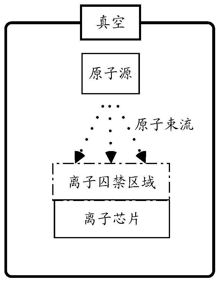
[0118] Such as Figure 8Shown is a schematic structural diagram of another ion trapping device provided in this application. In the ion trapping device, the atom generation module, the atom trapping module (taking 3D-MOT as an example) and the ion trapping module are all arranged in the third vacuum chamber. In a possible implementation manner, the distance between the first region in the atom trapping module and the ion chip in the ion trapping module satisfies within the second preset range S. The second preset range needs to satisfy that atoms are not easily deposited on the ion chip. Through the second example, being arranged in the same vacuum chamber helps to reduce the complexity of the vacuum system and the complexity of transferring atomic groups.
[0119] combined with the above Figure 8 The ion trapping device shown, as Figure 9a to ...
example 3
[0124] Example three, the combination of the first vacuum cavity and the second vacuum, the first optical trap laser.
[0125] The structure of the ion trapping device in this example can be compared with the above Figure 6 The structure of the ion trapping device shown is the same, see above Figure 6 description of.
[0126] combined with the above Figure 6 The ion trapping device shown, as Figure 10a to Figure 10c , exemplarily shows the process of transferring atomic groups from the atomic cooling trapping module to the ion trapping region in the ion trapping module by another optical trapping laser device. Specifically: the optical trap laser module is used to align the beam waist of the first optical trap laser with the first region (i.e., the center of the 3D-MOT) in the atom trapping module, and load the atomic groups in the first optical trap laser (such as Figure 10a ). The optical trap laser module transfers the beam waist of the first optical trap laser fr...
PUM
 Abstract
Description
Claims
Application Information
 - R&D
- Intellectual Property
- Life Sciences
- Materials
- Tech Scout
- Unparalleled Data Quality
- Higher Quality Content
- 60% Fewer Hallucinations
Browse by: Latest US Patents, China's latest patents, Technical Efficacy Thesaurus, Application Domain, Technology Topic, Popular Technical Reports.
© 2025 PatSnap. All rights reserved.Legal|Privacy policy|Modern Slavery Act Transparency Statement|Sitemap|About US| Contact US: help@patsnap.com