
Heat dissipation device and intelligent glasses equipment

A technology of heat dissipation device and smart glasses, which is applied to the structural parts of electrical equipment, cooling/ventilation/heating transformation, modification through conduction heat transfer, etc. problems, etc.

Active Publication Date: 2021-04-30
BEIJING XLOONG TECH CO LTD
View PDF5 Cites 0 Cited by
  • Summary
  • Abstract
  • Description
  • Claims
  • Application Information

AI Technical Summary

Problems solved by technology

[0005] In view of the above defects, the technical problem to be solved by the present invention is to provide a heat dissipation device and smart glasses equipment to solve the problems existing in the current technology that the heat cannot be discharged from the inside to the outside, the heat dissipation effect is not good, and the wind noise of the fan causes noise pollution. Problems with wearing experience

Method used


Image

  • Heat dissipation device and intelligent glasses equipment
  • Heat dissipation device and intelligent glasses equipment
  • Heat dissipation device and intelligent glasses equipment

Examples


Embodiment 1

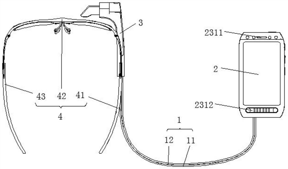
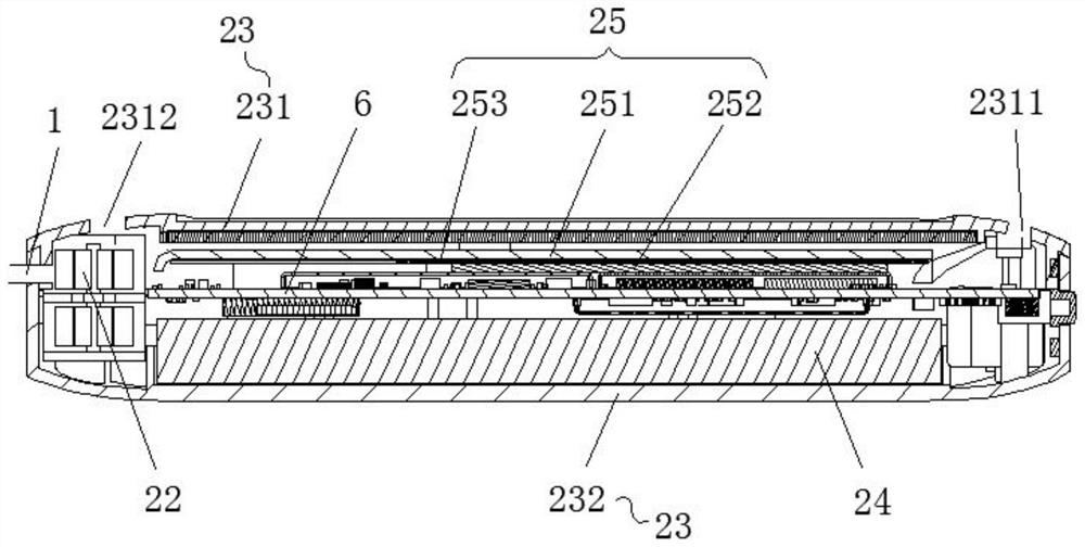
[0043] Please also refer to Figure 1 to Figure 3 Now, a specific implementation of a heat dissipation device provided by the present invention will be described. This heat dissipation device includes a connection line 1, a control radiator 2 and a wearing radiator 3, wherein the connection line 1 is provided with an electrical signal line 11 and an airflow channel line 12; the control radiator 2 is connected with the connection line 1 and is provided with a control container Cavity 21 and air blower 22; wearing radiator 3 is connected with connection line 1, and is provided with wearing cavity 31, and wearing cavity 31 communicates with control cavity 21 through airflow passage line 12.

[0044] The control radiator 2 can be held by hand or placed in other convenient or fixed positions. This is the operation end; the wearable radiator 3 is connected to the smart device, such as the frame part of smart glasses, which is the part that mainly contacts with the human body. This i...

Embodiment 2

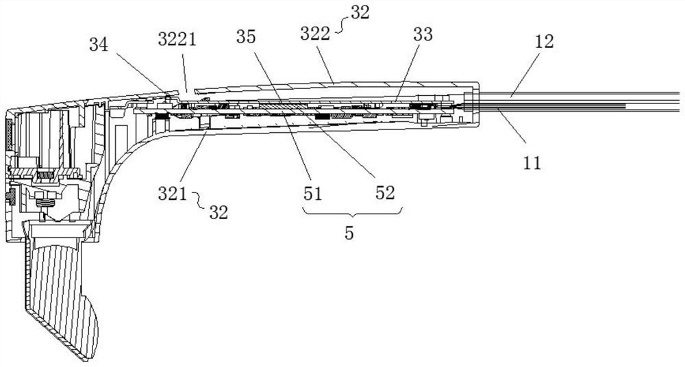
[0048]As a specific implementation of the embodiments of the present invention, please refer to Figure 1 to Figure 3 , the structure of a heat dissipation device provided by this embodiment is basically the same as that of Embodiment 1, the difference is that the wearing radiator 3 includes a wearing case 32, a heat dissipation plate 33 and a baffle plate 34, wherein the wearing case 32 is connected to The line 1 is connected to the heat dissipation element of the wearing end; the heat dissipation plate 33 is connected to the heat dissipation element of the wearing end through the heat conduction member 35; The heat dissipation plate 33 can be a heat dissipation copper plate; the heat conduction member 35 can be heat conduction silicone grease, which has good heat conduction performance and efficient heat dissipation. The baffle plate 34 is disposed near the heat dissipation holes 3221 to play a role in guiding the airflow, and guide the airflow to flow out from the upper hea...

Embodiment 3

[0054] As a specific implementation of the embodiments of the present invention, please refer to Figure 1 to Figure 3 , the structure of a cooling device provided by this embodiment is basically the same as that of Embodiment 2, the difference is that the control radiator 2 also includes an air suction device, which is arranged in the control cavity 21 for diverting the air flow It is sucked into the operating end by the wearing end, and then released from the air outlet 2311, so as to realize the gas flow and achieve the effect of heat dissipation. This setting is only an implementation of the airflow blowing from the wearing end to the operating end. Here, as long as it can realize the related performance effects of the above-mentioned inhalation device, it is within the scope of protection of this application document.


PUM


Abstract

The invention discloses a heat dissipation device. The heat dissipation device comprises a connecting wire, a control radiator and a wearable radiator, wherein the connecting wire is provided with an electric signal wire and an airflow channel wire; the control radiator is connected with the connecting wire and is provided with a control accommodating cavity and an air supply device; the wearable radiator is connected with the connecting wire and provided with a wearable containing cavity, and the wearable containing cavity is communicated with the control accommodating cavity through an airflow channel line. The invention further discloses intelligent glasses equipment which comprises the heat dissipation device, the surface shell temperature of the wearing end and the surface shell temperature of the operation end are controlled to be within an acceptable range, so that a user has good temperature rise experience; meanwhile, the local temperature is prevented from being too high, and good performance experience of the intelligent glasses is achieved. Function distribution is realized through separate arrangement of the control end and the wearing end, so that heat generated by the wearing end is controlled, the airflow is introduced into the control end through the airflow channel line, noise pollution caused by arrangement of a fan at the wearing end is avoided, and the heat dissipation device is simple in structure, remarkable in action effect and suitable for wide popularization.

Description

technical field [0001] The present invention relates to the technical field of smart equipment, in particular to a heat dissipation device and smart glasses equipment. Background technique [0002] Smart devices, especially smart glasses, are becoming smaller and more integrated, but due to the diversification of functions and the miniaturization of integrated circuit manufacturing, the power consumption of the device is high and concentrated in the IC (Integrated Circuit Chip micro Electronic devices), most of the power consumption is converted into heat, but the device cannot provide sufficient heat dissipation space, causing the heat concentration of the device and the local temperature is too high; at the same time, due to the close contact of the wearable device with the skin, the temperature requirements for the shell of the device very high. [0003] At present, most smart glasses connect the position of the chip on the main board with the heat sink with an interface...

Claims


Application Information

Patent Timeline
IPC IPC(8): H05K7/20G02B27/01
CPCH05K7/20145H05K7/2039G02B27/017G02B2027/0178Y02D10/00
Inventor 王生李双龙宋志亮杨义史晓刚
Owner BEIJING XLOONG TECH CO LTD
Learn More