
High-temperature pipeline vibration reduction device with guide bracket and vibration reduction method

A technology for guiding brackets and vibration damping devices, which is applied in the directions of pipeline brackets, pipe components, pipes/pipe joints/pipe fittings, etc., can solve problems such as personnel burns, affecting the safe and stable operation of nuclear power plant units, and failing to meet emergency defect processing time requirements.

Pending Publication Date: 2021-05-04
JIANGSU NUCLEAR POWER CORP
View PDF11 Cites 2 Cited by
  • Summary
  • Abstract
  • Description
  • Claims
  • Application Information

AI Technical Summary

Problems solved by technology

[0003] (1) Long-term vibration of high-temperature pipelines produces fatigue fractures, which affects the safe and stable operation of nuclear power plant units;
[0004] (2) If the high-temperature pipeline is damaged and cracked due to fatigue, the high-temperature medium will leak and there is a risk of burns;
[0006] (1) For high-temperature pipelines, due to thermal expansion and thermal displacement, it is usually necessary to add a damper, but the damper needs to be customized according to the pipeline conditions, and the manufacturing and procurement cycle is long (usually more than half a year), which cannot meet the processing time for urgent defects Requirements, high time cost and economic cost;
[0007] (2) If the vibration defect is not resolved, it is necessary to select the damper again or take other corrective measures, resulting in economic losses

Method used


Image

  • High-temperature pipeline vibration reduction device with guide bracket and vibration reduction method
  • High-temperature pipeline vibration reduction device with guide bracket and vibration reduction method

Examples


Embodiment Construction

[0031] The vibration damping device and vibration damping method for a high-temperature pipeline with a guide bracket provided by the present invention will be further described in detail below with reference to the accompanying drawings and specific embodiments.

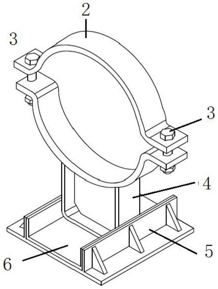
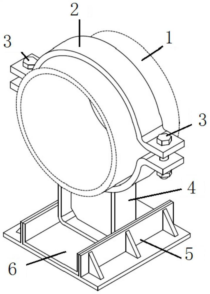
[0032] Such as figure 1 As shown, the present invention provides a high-temperature pipeline damping device with a guide bracket, including an upper pipe clip 2, a locking bolt 3, a lower pipe clip 4, a guide base 5, a polytetrafluoroethylene pad 6, and an upper pipe clip 2 The upper and lower pipe clips 4 are all semicircular structures, with protruding bolt holes respectively provided on both sides, and connected by locking bolts 3; Cooperate; the bottom of the lower pipe clamp 4 is welded with a guide track matching the guide base 5, the guide track is embedded in the guide base 5, and a polytetrafluoroethylene pad 6 is laid in the guide base 5.

[0033] This method comprises the following steps:

[0034] Step ...


PUM


Abstract

The invention belongs to the technical field of high-temperature pipeline vibration treatment, and particularly relates to a high-temperature pipeline vibration reduction device with a guide bracket and a vibration reduction method. The high-temperature pipeline vibration reduction device with the guide bracket comprises an upper pipe clamp, locking bolts, a lower pipe clamp, a guide base and a polytetrafluoroethylene pad, wherein the upper pipe clamp and the lower pipe clamp are both of semicircular structures; protruding bolt holes are formed in the two sides of the upper pipe clamp and the two sides of the lower pipe clamp respectively; the upper pipe clamp and the lower pipe clamp are connected through the locking bolts, and then the interior of the connected upper pipe clamp and lower pipe clamp is matched with a high-temperature process pipeline in shape; a guide rail matched with the guide base is welded to the bottom of the lower pipe clamp and embedded into the guide base; and the polytetrafluoroethylene pad is laid in the guide base. According to the high-temperature pipeline vibration reduction device with the guide bracket and the vibration reduction method provided by the invention, the high-temperature pipeline vibration reduction device has high feasibility and universality, can replace a damper to conduct vibration reduction on a high-temperature pipeline, and is short in implementation period and high in economic benefit.

Description

technical field [0001] The invention belongs to the technical field of high-temperature pipeline vibration control, and in particular relates to a high-temperature pipeline vibration damping device with a guide bracket and a vibration damping method. Background technique [0002] For the pipelines of the power station process system, due to the influence of many factors such as design defects, changes in working conditions, and unreasonable layout of supports and hangers, the pipelines will have high vibration problems. Among them, the vibration problem of high-temperature pipelines is the most sensitive. If relevant measures are not taken in time Vibration dampening measures can cause: [0003] (1) Long-term vibration of high-temperature pipelines produces fatigue fractures, which affects the safe and stable operation of nuclear power plant units; [0004] (2) If the high-temperature pipeline is damaged and cracked due to fatigue, the high-temperature medium will leak and ...

Claims


Application Information

Patent Timeline
IPC IPC(8): F16L55/035F16L3/10
CPCF16L55/035F16L3/10
Inventor 朱军刘文超荀蔚卢仲轩秦贯洲周正平
Owner JIANGSU NUCLEAR POWER CORP
Learn More