Mop capable of squeezing water at two ends and assembly thereof

A mop and component technology, which is applied in cleaning carpets, floors, cleaning equipment, etc., can solve the problems of not easy to squeeze dry, easy to damage the foam head, and increase the burden on the user's body, so as to improve the shrinkage speed and reset speed, Enrich the use environment and enhance the effect of experience

Pending Publication Date: 2021-05-07
夏陈攀 +1
View PDF2 Cites 0 Cited by
  • Summary
  • Abstract
  • Description
  • Claims
  • Application Information

AI Technical Summary

Problems solved by technology

The disadvantage of this dehydration method is that in the process of squeezing water, the user needs to bend down to pull the handle structure, and at the same time, the mop needs to be lifted, which increases the physical burden of the user on the one hand, and reduces the use efficiency on the other hand; After using this kind of mop for a long time, only a lot of force can be used to effectively squeeze out the moisture, so the use effect after long-term use is greatly reduced
However, it needs to squeeze and slide over the foamed cotton head when squeezing water, which is easy to damage the foamed cotton head and is not easy to squeeze out the water, which affects the user experience

Method used


Image

  • Mop capable of squeezing water at two ends and assembly thereof
  • Mop capable of squeezing water at two ends and assembly thereof
  • Mop capable of squeezing water at two ends and assembly thereof

Examples


Embodiment 1

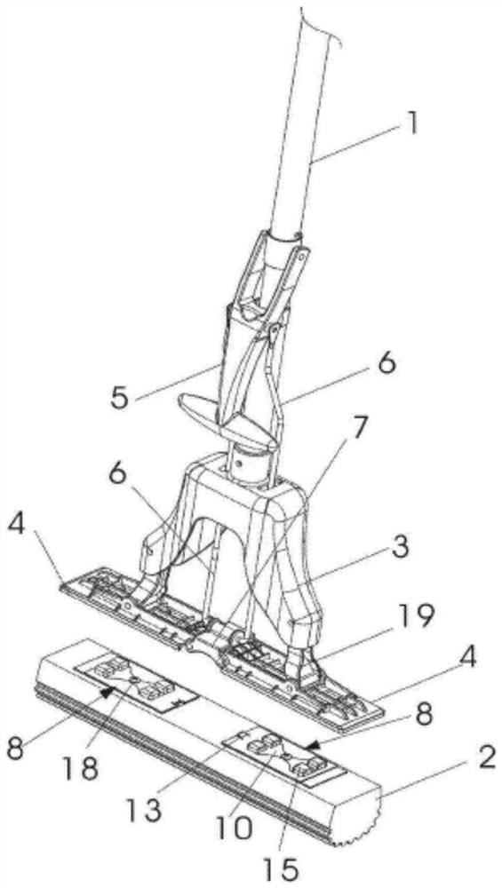
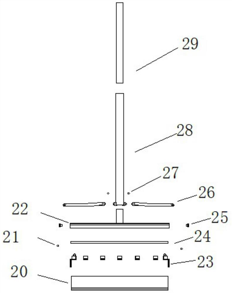
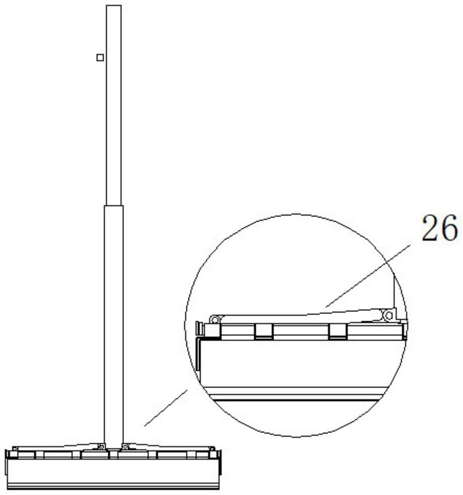
[0035] Such as Figure 2-5 As shown, the present embodiment provides a mop including a collodion head 20, a rotating shaft 21 or 27, a mop panel 22, a mounting block 23, a track 24, a plug 25, a moving arm 26, a grip 28 and a mop rod 29.

[0036] In this embodiment, the outer diameter of the mop rod 29 should be slightly smaller than the inner diameter of the handle 28, so that the mop rod 29 can be smoothly put into the handle 28 and can be pulled flexibly in the handle 28. The mop panel 22 is provided with a groove for the movement arm 26 to pass through, while the mop panel 22 both sides are provided with plugs 25, and the middle part of the upper end face of the mop panel 22 is fixedly connected with the pipe 29 to realize the overall positioning of the mop. A plug 25 is provided, and the plug 25 is used to limit the lateral movement of the moving arm 27, and at the same time prevent sundries from entering the interior of the mop head. figure 2 The track 24 shown in the ...

Embodiment 2

[0043] refer to Figure 6-11 As shown, the difference between this embodiment and Embodiment 1 is that six spring structures 34 are arranged on the sliding track, and three spring structures are respectively arranged on the left and right sides. The flexibility and other aspects are adjusted. The middle part of the upper end surface of the mop panel is rotated with a short rod structure, and the lower rod 37 is fixedly connected with the short rod. Structures such as auxiliary wheels 36 and steel wire ropes 35 are provided, through which the automatic return of the collodion head 31 can be realized and the convenience of use can be improved.

[0044] Such as Figure 6 As shown, the spring 34 is arranged on the track, and the spring can realize compression and reset along the track, and the steel wire rope 35 bypasses the structure of the auxiliary wheel 36 to realize the change of the extension direction of the steel wire rope and reduce friction loss at the same time.

[0...

Embodiment 3

[0051] refer to Figure 12-16 , The mop provided in this embodiment includes any collodion head, track, and mop panel structure as described above, and also includes the short rod structure in Embodiment 2, which can realize the rotation of the mop rod.

[0052] The difference from the previous two embodiments is that there are grooves inside the mounting blocks 40 on both sides, and an inclined slope structure is arranged inside the grooves, which can be used with a squeeze bucket, and there are protruding parts 44 inside the squeeze bucket as abutment part, the bottom of the protruding part 44 is fixedly connected with the inner bottom of the squeezing bucket. During the water squeezing process, the upper side of the protruding part 44 cooperates with the inclined slope of the groove to realize the inward movement of the mounting blocks 40 on both sides.

[0053] In this embodiment, the spring structure of Embodiment 2 can be set on the track, and the corresponding spring c...


PUM


Abstract

The invention discloses a mop capable of squeezing water at two ends and an assembly thereof. The mop comprises a wiping part, a mop face plate and a mop rod, the mop face plate is arranged at the lower end of the mop rod, a track is fixedly installed below the mop face plate, the track is sleeved with installation blocks, the two installation blocks on the outermost side are provided with stress plates respectively, and the water squeezing of the two ends of the mop is achieved by squeezing the stress plates at the two ends. Besides the mop structure, the mop further comprises a water squeezing barrel structure matched with the mop structure, and the functions of water squeezing and water storage are achieved through the mop and the water squeezing barrel structure. By means of the structure, the problems that an existing water squeezing mop is low in efficiency, limited in service life and the like are solved, a user can be easily helped to squeeze out water in the wiping part, and the mop is more convenient for the user to use.

Description

technical field [0001] The invention relates to the field of daily necessities, in particular to cleaning appliances, and more specifically to a mop and its components. Background technique [0002] The mop is a cleaning tool that people often use in daily life. Currently, there are two kinds of mops on the market: cloth belt mop and collodion mop. The cloth belt mop is usually equipped with a drying bucket structure. When the moisture on the mop is removed, the mop head is put into the drying barrel and rotated to dry. This mop structure usually needs to occupy more space due to the structure of the drying barrel, which brings inconvenience to use. [0003] At present, the popularity rate of collodion mop in daily life is getting higher and higher. Its main structure is roughly the same, including mop rod, mop head and water squeezing device. The water squeezing device can be folded in half through the relative movement of the mop rod and mop head. Thereby squeezing out th...

Claims


Application Information

Patent Timeline
Patent Type & Authority Applications(China)
IPC IPC(8): A47L13/254A47L13/14A47L13/42A47L13/58
CPCA47L13/14A47L13/254A47L13/42A47L13/58
Inventor 夏陈攀
Owner 夏陈攀
Why Eureka
Try Eureka