
Concrete pouring device for building construction

A construction and concrete technology, applied in the field of concrete pouring, can solve the problems of inability to automatically adjust the pouring direction and pouring height, affecting the subsequent treatment of concrete, low concrete pouring quality, etc., to achieve good mixing effect, sufficient and comprehensive mixing, guaranteeing The effect of pour quality

Pending Publication Date: 2021-05-07
温林坤
View PDF9 Cites 1 Cited by
  • Summary
  • Abstract
  • Description
  • Claims
  • Application Information

AI Technical Summary

Problems solved by technology

[0003] The following problems exist in the existing concrete pouring device: a: the existing concrete pouring device cannot control the amount of feed, and too much feed at one time may cause the device to be blocked, which affects the follow-up treatment of concrete and reduces work efficiency; b : the mixing mechanism that existing concrete pouring device is provided with can't fully mix concrete, causes the pouring quality of concrete to be lower, has reduced work efficiency; c: existing concrete pouring device can not automatically adjust the direction and pouring height of pouring, It is necessary to manually change the position of the equipment to adjust the pouring direction, which reduces the work efficiency

Method used


Image

  • Concrete pouring device for building construction
  • Concrete pouring device for building construction
  • Concrete pouring device for building construction

Examples


Embodiment 1

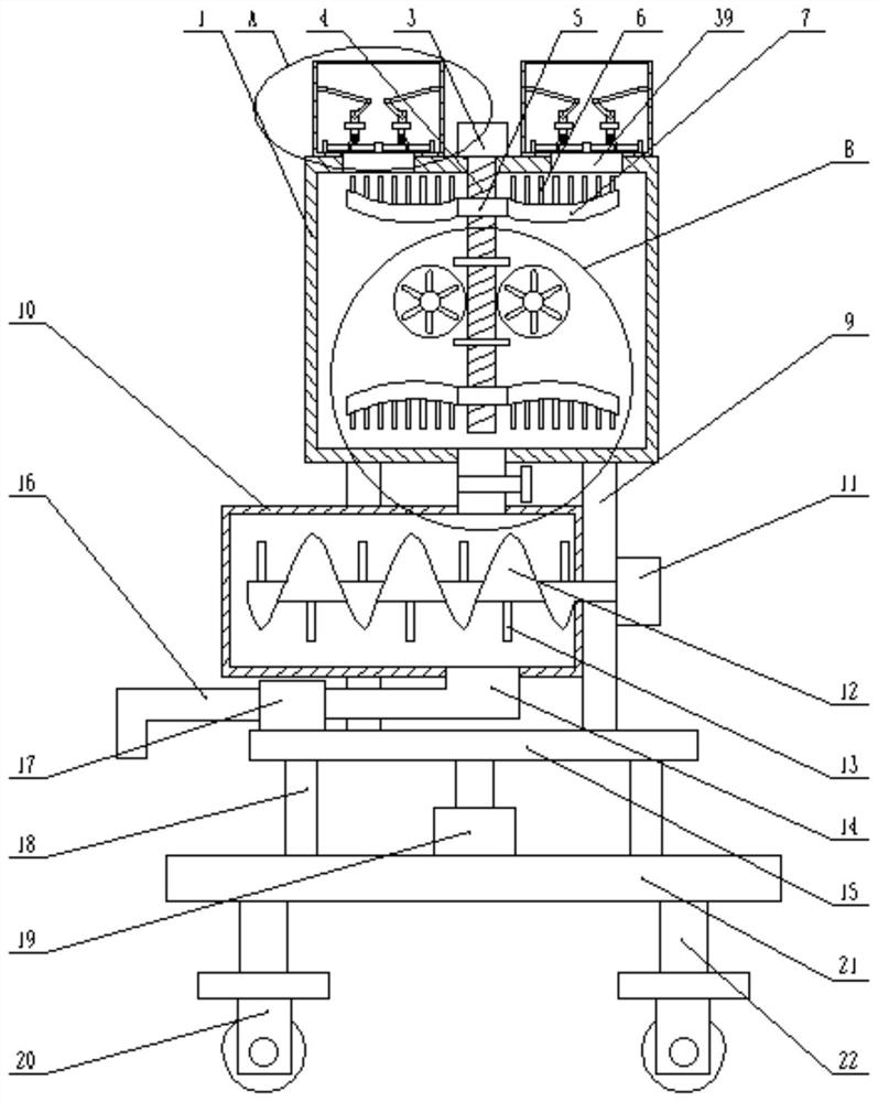
[0022] see Figure 1~Figure 4 As shown, a concrete pouring device for building construction includes a base plate 21, an execution cylinder 22 is arranged on the outer wall at the four corners at the bottom of the base plate 21, and a roller 20 is arranged on the outer wall of the bottom end of the execution cylinder 22, and the top ends of the base plate 21 are Thrust ball bearings 18 are symmetrically arranged on the outer wall, and a support plate 15 is arranged on the outer wall of the top end of the thrust ball bearing 18, and an actuator motor 19 installed on the outer wall of the top middle part of the bottom end of the support plate 15 is arranged on the outer wall of the bottom middle of the support plate 15, and the top of the support plate 15 Support legs 9 are symmetrically arranged on the outer walls of both ends, and a processing box 1 is arranged on the outer wall of the top end of the supporting legs 9, and a feeding box 24 is symmetrically arranged on the outer...

Embodiment 2

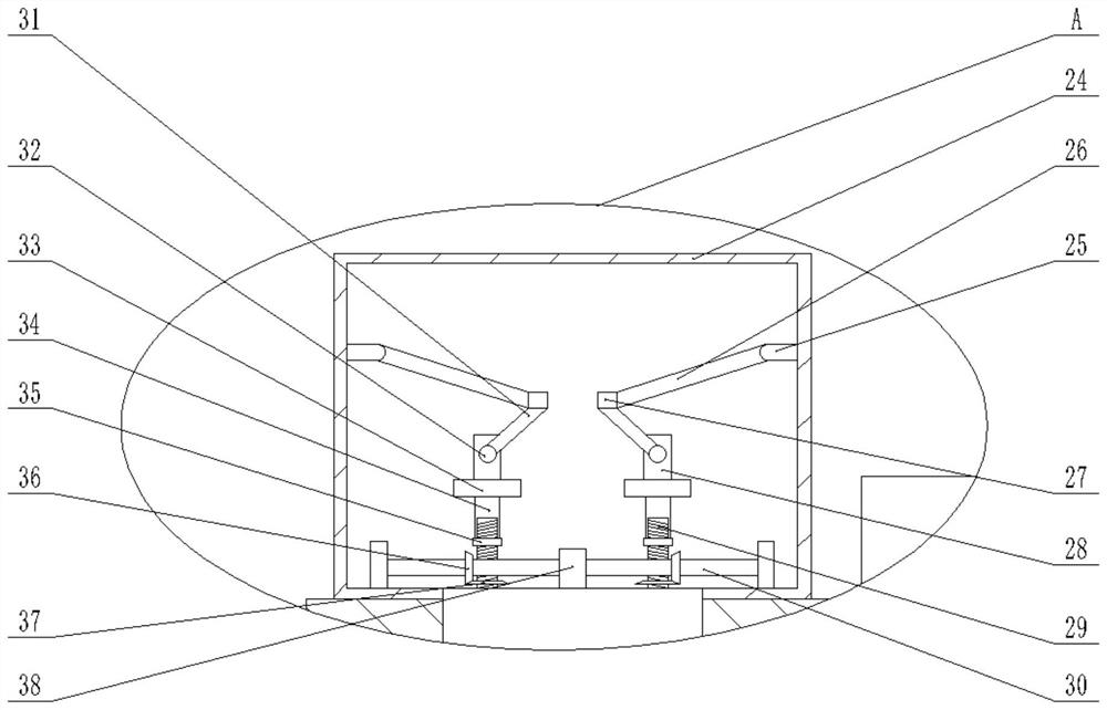
[0029] On the basis of embodiment one, refer to Figure 4 The outer wall of the front side of the processing box 1 is provided with a cover plate 23, the outer wall of the top left end of the front side of the cover plate 23 is provided with a control panel 2, and the outer wall of the bottom end of the front side of the cover plate 2 is symmetrically provided with a transparent glass window 8; by setting The cover plate 23 is convenient for inspection and maintenance of the inside of the processing box 1. Intelligent control can be realized by setting the control panel 2, which reduces manpower operations and improves work efficiency. It is convenient to observe the working conditions inside the processing box 1 by setting the transparent glass window 8.

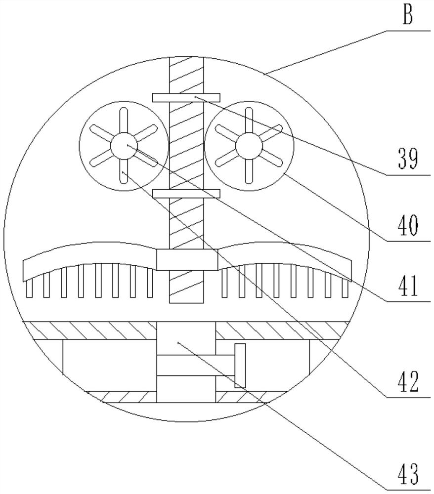
[0030] Working principle: In the process of use, by setting the feed box 24, the rotating shaft 25, the baffle plate 26, the connecting block 27, the double-axis motor 38, the rotating shaft 30, the driving screw 29, the fir...


PUM


Abstract

The invention relates to the technical field of concrete pouring, in particular to a concrete pouring device for building construction. The concrete pouring device comprises a bottom plate, execution cylinders are arranged on the outer walls of four corners of the bottom of the bottom plate, and rolling wheels are arranged on the outer walls of the bottom ends of the execution cylinders. The concrete pouring device is novel in structure, by arranging a worm, a sliding sleeve, a stirring rod, a stirring plate, a turbine, a stirring shaft and a stirring wheel, stirring in the vertical direction and the horizontal direction can be achieved, the stirring range is changed, concrete can be fully and comprehensively stirred, the stirring effect is improved, the pouring quality of the concrete is guaranteed, by arranging a conveying spiral screw, a vertical rod and a rotating motor, when the conveying spiral screw rotates, on one hand, the concrete can be conveyed, on the other hand, secondary stirring can be conducted on the concrete, the good stirring effect is achieved, the concrete can be mixed more evenly, the pouring quality of the concrete is improved, and the working efficiency is improved.

Description

technical field [0001] The invention relates to the technical field of concrete pouring, in particular to a concrete pouring device for building construction. Background technique [0002] Concrete pouring equipment is a machine that uses pressure to continuously convey concrete along the pipeline. It is composed of a pump body and a conveying pipe. According to the structure, it is divided into piston type, extrusion type, and hydraulic diaphragm type. Equipped with a telescopic or inflected placing boom, a pump truck is formed. The concrete pouring equipment is transformed from a load-bearing chassis, which is equipped with a movement and power transmission device, a pumping and stirring device, and a distribution device And some other auxiliary devices, the power of the concrete pouring equipment transmits the power of the engine to the hydraulic pump group or the rear axle through the power transfer case, the hydraulic pump pushes the piston to drive the concrete pump to...

Claims


Application Information

Patent Timeline
IPC IPC(8): B28C5/16B28C5/08B28C5/14B28C7/16E04G21/04
CPCB28C5/16B28C5/0806B28C5/142B28C7/167E04G21/04
Inventor 温林坤
Owner 温林坤
Features
  • Generate Ideas
  • Intellectual Property
  • Life Sciences
  • Materials
  • Tech Scout
  • Unparalleled Data Quality
  • Higher Quality Content
  • 60% Fewer Hallucinations
Learn More