Guide device capable of implementing spatial dislocation conveying and non-woven fabric forming machining mechanism

A guiding device and space technology, applied in the directions of transportation and packaging, sending objects, winding strips, etc., can solve the problems of large device footprint, low operation coordination efficiency, and high device investment cost

Active Publication Date: 2021-05-07
福建宇邦纺织科技有限公司
View PDF10 Cites 2 Cited by
  • Summary
  • Abstract
  • Description
  • Claims
  • Application Information

AI Technical Summary

Problems solved by technology

It can be seen that when it is necessary to use the same billet for different post-processing processes to obtain different products, it is impossible to integrate the process of the devices that require different post-processing in the front feeding section, and the efficiency of operation synergy is low and the resulting equipment Technical problems of large floor area and high equipment investment cost

Method used


Image

  • Guide device capable of implementing spatial dislocation conveying and non-woven fabric forming machining mechanism
  • Guide device capable of implementing spatial dislocation conveying and non-woven fabric forming machining mechanism
  • Guide device capable of implementing spatial dislocation conveying and non-woven fabric forming machining mechanism

Examples


Embodiment 1

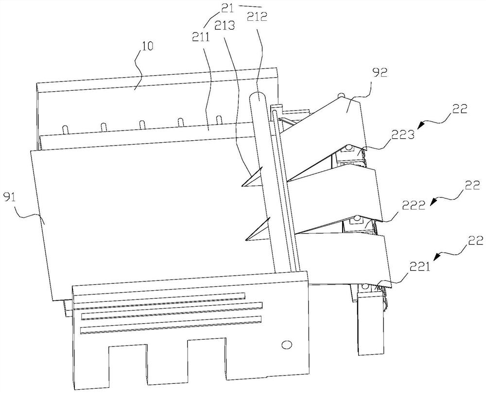
[0070]Such asfigure 1 As shown, the present embodiment discloses a guiding device for spatial misalignment transportation, in accordance with the order of the process flow from the process, sequentially include the division cutting device 21, the guide 22.

[0071]The dividing device 21 includes a slitting platform 211, a slitting shaft 212, a slit cutter 213, and a slit cutter 213 is located above the slitting platform 211, and the slit cutter 213 is fixed to the slitting shaft 212, and the slitting shaft 212 rotates The rack 10 is on.

[0072]The material 91 is divided into a sub-material strip 92 having the same amount as the guide 22 of the guide 22 by dividing the cutter 213. When the driving device drives the adjacent guide 22 to generate a high difference, the different sub-material strips 92 after separating the cutter 213 can pass through different guide 22. When the drive device drives the guide roller in the adjacent guide 22, the tail contact in the adjacent guide 22 is in con...

Embodiment 2

[0103]Such asFigure 11 ,12As shown, the difference from the above-described embodiment is that the cutting head mounting groove 2111 is opened upward on the dividing stage 211. The splitter 213 can be rotated to its cutter head into the corresponding tool head mounting groove 2111. The tightening tank 2161 is rotated on the partial cut platform 211, and the fastening screw 2161 is threaded through the cutter head mounting groove 2111. The left block 2162 is limited in the cutter head mounting groove 2111, the right block 2163. The left block 2162, the right block 2163 is both threaded with the fastening screw rod 2161, and the threaded direction of the fastening screw 2161 cooperates with the left block 2162 and the fastening screw 2163 cooperate with the right block 2163. A thread is backwards. When the cutter 213 is rotated to its cutter head to the corresponding cutter head mounting groove 2111, the left block 2162, the right block 2163, the right block 2163, the right block 2163...

Embodiment 3

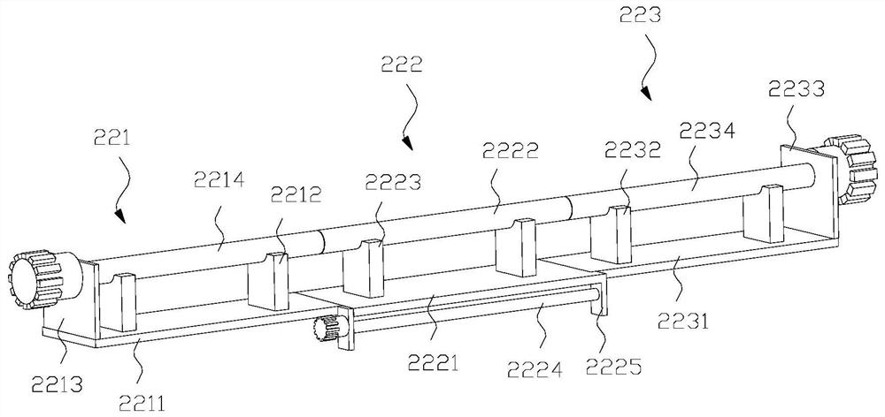
[0113]Such asFigure 14-18 As shown, the difference from the above-described embodiment is that a set of locking linkages are provided on the left guide roller 2214, and the right side guide roller 2234 is provided.

[0114]The left opening of the left guide roller 2214 is opened at the right end surface of the left guide roller 2214, and the left end surface of the right guide roller 2234 is in communication with the uppermost opening of the hollow structure in the right guide roller 2234.

[0115]The locking linkage includes a linkage rod 201, a connection key 202, a sliding block 203.

[0116]The linkage rod 201 is rotated in a fixed mount 209 fixed in a corresponding hollow structure, and the sliding block 203 is fixed to the connection key 202 and the sliding block 203 is coordinated with the linkage rod 201.

[0117]The linkage rod 201 of the rotating left guide roller 2214 can cause a limit to the left open opening and extend to the left to the left end of the left end portion of the inte...


PUM


Abstract

The invention discloses a guide device capable of implementing spatial dislocation conveying. In the process that a driving device drives adjacent guide devices to generate a height difference, a pressing roller can be linked to move downwards to press on a sub-material strip, and the pressing roller can be linked to move upwards in sequence; after the pressing roller is lifted, different sub-material strips slit by a slitting knife can sequentially pass through a gap between the pressing roller and a slitting platform and different guide devices; when the driving device drives guide rollers in the adjacent guide devices to be mutually horizontal, the guide rollers in the adjacent guide devices are in end-to-end contact to form an integral guide roller structure; and materials can sequentially pass through the gap between the pressing roller and the slitting platform and the integral guide roller structure. The invention further discloses a non-woven fabric forming machining mechanism. The device has the advantages that different post-treatments are carried out on the same blank in the same machining production line to improve the device integration and the process collaboration.

Description

Technical field[0001]The present invention relates to the field of textile technology, and more particularly to a guiding device for spatial misalignment delivery, non-woven forming processing mechanism.Background technique[0002]Belt materials such as various woven fabrics, knitted fabrics, nonwoven fabrics, plastic film processing, in order to improve their physical properties and given more functionality, it is often necessary to carry out postal processing, such as knife, immersion Treatment of rolling and multilayer layer composite.[0003]As the coater disclosed in 201621432168.0, the base fabric is taken to treat the base fabric, and a secure flap immersion mill disclosed in Patent Application No. 201210109531.5 is used to impat the fabric. A antibacterial composite fabric, which is disclosed, disclosed in Patent Application, 201811188431.x, and the preparation method thereof, by pressing the lower surface of the base fabric with the upper surface of the antibacterial composite ...

Claims


Application Information

Patent Timeline
Patent Type & Authority Applications(China)
IPC IPC(8): B65H35/02B65H20/02
CPCB65H35/02B65H20/02B65H2301/515323B65H2301/515326
Inventor 饶国超李泽辰罗志刚林英陈诗怡余亮
Owner 福建宇邦纺织科技有限公司
Why Eureka
Try Eureka