Defoaming device for biochemical treatment of sewage

A defoaming device and biochemical treatment technology, applied in water/sewage multi-stage treatment, degassed water/sewage treatment, water/sludge/sewage treatment, etc. The problem of large consumption, etc., can achieve the effect of reducing the operating failure rate, reducing moving parts, and high defoaming efficiency.

Active Publication Date: 2021-05-07
华夏锦绣环保(北京)有限公司
View PDF8 Cites 2 Cited by
  • Summary
  • Abstract
  • Description
  • Claims
  • Application Information

AI Technical Summary

Problems solved by technology

[0004] However, the traditional defoaming device has the following problems: (1) The waste water from the aerobic tank or other process steps is drawn. If it is not filtered, the mud-water mixture enters the end nozzle. Because it contains a large amount of sludge or sediment, the nozzle is often blocked. Moreover, when the nozzle itself runs for a long time, it is also easy to be attached and blocked by the sludge in the circulating wastewater; (2) For large-scale aerobic biochemical treatment tanks or devices, single-point liquid level gauges or large-scale foam scrapers are usually used at present, There are cases where foam detection is not timely or a large-scale foam scraper is used when there is only a small amount of foam, and multi-point detection and timely opening of the defoaming device cannot be achieved, resulting in foam overflow, affecting the defoaming effect, and greater energy consumption; ( 3) The traditional defoaming device, whether it is spray defoaming, spraying defoaming agent or physical foam scraping, usually uses multiple liquid pumps to transport different water bodies, and there are many moving parts, which not only consumes a lot of energy, but also is prone to failure
(4) For large sewage biochemical treatment tanks, the amount of defoamer added is relatively large, and the treatment cost is high

Method used


Image

  • Defoaming device for biochemical treatment of sewage
  • Defoaming device for biochemical treatment of sewage
  • Defoaming device for biochemical treatment of sewage

Examples


Embodiment 1

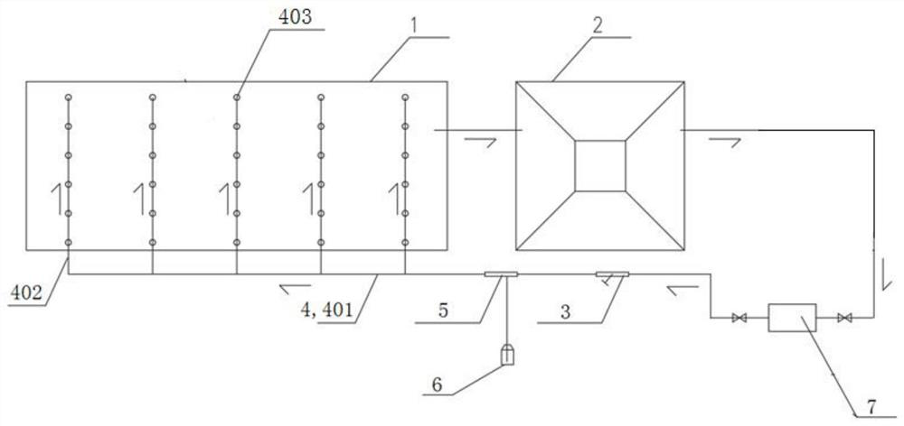
[0043] The defoaming device used for sewage biochemical treatment described in this embodiment, such as figure 1 As shown, it includes an aerobic tank 1, a sedimentation tank 2, a filter 3, a water injector 5 connected to a defoamer storage 6, and a spray pipeline 4. The aerobic tank 1 is connected to a sedimentation tank 2, and the sedimentation tank 2 is sequentially The spray pipeline 4 is connected with the circulation pump 7, the filter 3 and the water ejector 5, and the circulation pump 7 transfers the supernatant of the sedimentation tank 2 into the water ejector 5, and the water ejector 5 sucks the defoamer and mixes with the supernatant After mixing, enter the spray pipeline 4.

[0044] The spray pipeline 4 includes a main pipe 401 and five branch pipes 402 connected in parallel with it. The water inlet end of the main pipe 401 is connected to the water outlet end of the water ejector 5. The branch pipes 402 are perpendicular to the water flow direction in the aerobic...

Embodiment 2

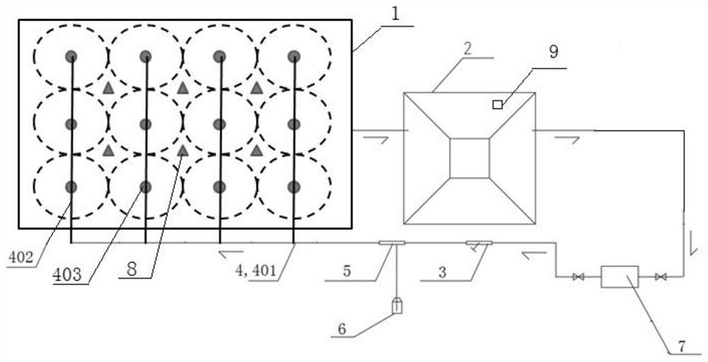
[0046] The defoaming device used for sewage biochemical treatment described in this embodiment, such as figure 2 and 3 As shown, it includes an aerobic tank 1, a sedimentation tank 2, a filter 3, a spray pipeline 4, and a water injector 5 connected to a defoamer storage 6. The aerobic tank 1 is connected to the sedimentation tank 2 through a pipeline, and biological treatment The final sewage enters the sedimentation tank 2 for mud-water separation, and the upper part of the sedimentation tank is the supernatant. The upper part of the sedimentation tank 2 is connected to the outlet pipe, and the sedimentation tank 2 is connected to the spray pipeline 4 through the circulation pump 7, the filter 3 and the water injector 5 in turn, and the circulation pump 7 inputs the supernatant of the sedimentation tank 2 into the water injector 5, The water ejector 5 inhales the defoamer and mixes it with the supernatant and then enters the spray pipeline 4; the supernatant of the sediment...

Embodiment 3

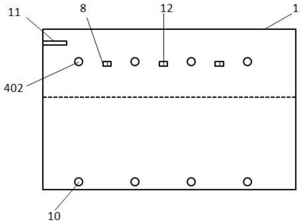
[0060] The defoaming device used for sewage biochemical treatment described in this embodiment, such as image 3 and 4 As shown, a pressure gauge 12 is added to the radio frequency admittance level switch, and the pressure gauge is connected to the control system as a supplement to the radio frequency admittance level switch.

[0061] Described defoaming device also comprises clear water tank 13 and the 3rd liquid level gauge 14, and clear water tank 13 is located at the downstream side of sedimentation tank 2, and is connected with sedimentation tank 2 by pipeline, and the outlet pipeline of clear water tank 13 is connected circulation pump 7, and the second Three liquid level gauges 14 are arranged in the clear water tank 13 to monitor the liquid level. The third liquid level gauge 14 is an ultrasonic liquid level gauge, and the third liquid level gauge 14 is connected to the control system. The supernatant in the sedimentation tank 2 is input into the clear water tank 13 f...


PUM


Abstract

The invention relates to a defoaming device for biochemical treatment of sewage, and the device comprises an aerobic tank, a sedimentation tank, a defoaming agent storage device and a spraying pipeline; the aerobic tank is connected with the sedimentation tank. The defoaming device is characterized in that the defoaming device further comprises a filter and a water ejector connected with the defoaming agent storage device; the sedimentation tank is connected with the spraying pipeline through the circulating pump, the filter and the water ejector in sequence, the circulating pump inputs supernate of the sedimentation tank into the water ejector, and the water ejector sucks a defoaming agent, mixes the defoaming agent with the supernate and inputs the mixture into the spraying pipeline; the spraying pipeline comprises a main pipe and a plurality of branch pipes connected with the main pipe in parallel, the water inlet end of the main pipe is connected with the water outlet end of the water ejector, the branch pipes are perpendicular to the water flow direction in the aerobic tank and distributed in the inner space of the aerobic tank, and a plurality of nozzles are arranged on each branch pipe at intervals and used for spraying mixed liquid of a defoaming agent and supernate.

Description

technical field [0001] The invention belongs to the technical field of sewage treatment, and in particular relates to a defoaming device for biochemical treatment of sewage. Background technique [0002] With the acceleration of urbanization, the living standards of people in cities and urban circles are constantly improving, and the amount of sewage generated by life or industry is also increasing year by year, which has caused greater pressure and higher requirements on sewage treatment and energy reuse systems. Biological sewage technology uses aerobic or anaerobic microorganisms to degrade organic pollutants in sewage, which is energy-saving and environmentally friendly. However, sewage with more organic pollutants, especially landfill leachate, will always have Foams are generated, if these foams are not treated in time, these foams will overflow the biochemical pool, causing secondary pollution. [0003] The traditional defoaming device used for sewage treatment is to...

Claims


Application Information

Patent Timeline
Patent Type & Authority Applications(China)
IPC IPC(8): C02F9/14B01D19/04
CPCB01D19/04C02F1/001C02F1/20C02F1/52C02F3/02C02F9/00C02F2001/007C02F2209/005C02F2209/42
Inventor 张传兵孙振洲赵曙光陈长松王慧芳徐亚萍王杰王天杰王强强侯亚平张冰代攀翟瑞锋乔丙林
Owner 华夏锦绣环保(北京)有限公司
Why Eureka
Try Eureka