Metasurface antenna with rectangular patch arrays arranged in staggered mode

A technology of rectangular patches and staggered arrangement, applied in the field of communication antennas, can solve the problems of complex antenna design and unstable performance

Inactive Publication Date: 2021-05-07
SUN YAT SEN UNIV
View PDF11 Cites 1 Cited by
  • Summary
  • Abstract
  • Description
  • Claims
  • Application Information

AI Technical Summary

Problems solved by technology

The existing method to improve the gain of the traditional patch antenna is to directly load the metasurface on top of the antenna, but this antenna has a double-layer structure, and there is a risk of unstable performance
[0003] The publication date is November 24, 2017, and the Chinese patent with the publication number CN107394381A discloses a low-profile broadband circularly polarized array antenna based on stacked traveling wave antenna units, including: three segments connected end to end and printed on both sides of the dielectric board Circularly polarized antenna unit composed of the metal layer on the side and metallized through-holes connecting the two layers, 2×2 antenna sub-array composed of metallized through-hole cavity and 4 antenna units, 16 antenna sub-array composed of metalized through-holes The full parallel feed network, the gap between the feed layer and the metal cavity and the antenna for coupling feed, the grounded coplanar waveguide (Grounded Coplanar Waveguide, GCPW) and the substrate integrated waveguide (Substrate Integrated Waveguide, SIW), but the design of the antenna is more complicated

Method used


Image

  • Metasurface antenna with rectangular patch arrays arranged in staggered mode
  • Metasurface antenna with rectangular patch arrays arranged in staggered mode
  • Metasurface antenna with rectangular patch arrays arranged in staggered mode

Examples


Embodiment 1

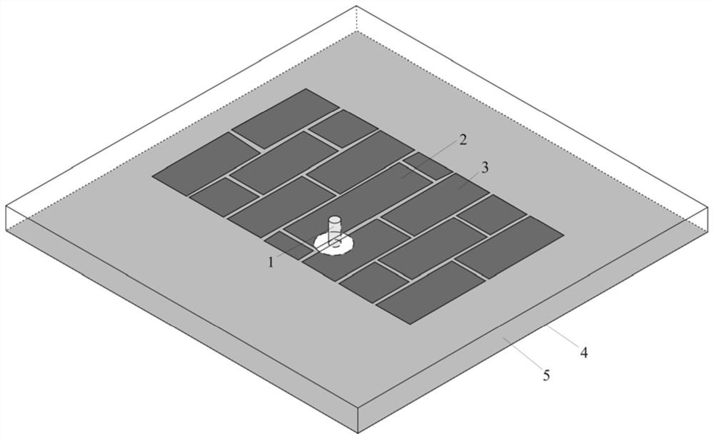
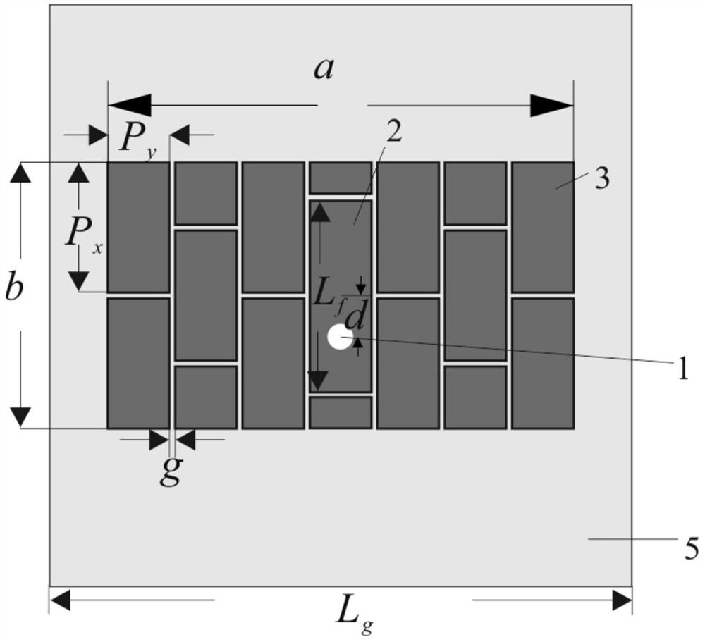
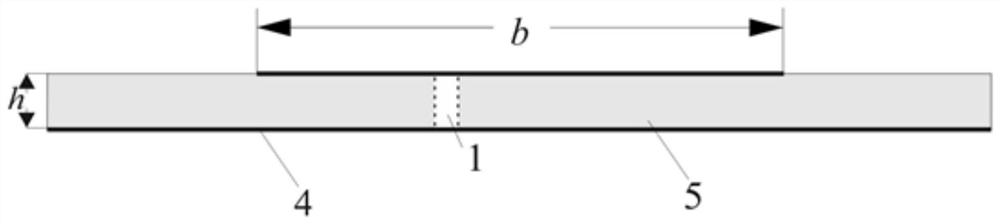
[0034] This embodiment provides a metasurface antenna in which rectangular patch arrays are staggered, such as Figure 1 to Figure 3 , including a metal ground plate 4, a dielectric substrate 5, a metasurface and a feeding probe 1, wherein the metasurface is disposed on the upper surface of the dielectric substrate 5, and the metal ground plate 4 is disposed on the dielectric substrate 5 The lower surface of the metasurface includes a staggered array of rectangular patches, the driving rectangular patch 2 at the center is used as a driving unit, and the other is a coupling rectangular patch 3, which is a coupling unit. The electrical probe 1 runs through the metasurface and the dielectric substrate 5 longitudinally, and connects with the rectangular patch at the center.

[0035] The range of the rectangular patch array is specifically set as:

[0036] With the size of the coupling rectangular patch 3 as the coupling unit, a 2×7 array of rectangular patch arrays is arranged. ...


PUM


Abstract

The invention provides a metasurface antenna with rectangular patch arrays arranged in a staggered mode. Theantenna comprises a metal grounding plate, a dielectric substrate, a metasurface and a feed probe. The metasurface is arranged on the upper surface of the dielectric substrate, the metal grounding plate is arranged on the lower surface of the dielectric substrate, the metasurface comprises a rectangular patch arrays arranged in a staggered mode, a rectangular patch in the center of the metasurface serves as a driving unit, other rectangular patches serve as coupling units, and the feed probe longitudinally penetrates through the metasurface and the dielectric substrate and is connected with the rectangular patch in the center. According to the metasurface, a similar microstrip patch technology is adopted, the metasurface is easy to integrate and machine, and a profile is low; and by introducing the metasurface, the structure not only can generate the broadband characteristic of double resonant frequency points, but also improves a gain of the traditional patch antenna. Meanwhile, the structure realizes suppression of cross polarization on a vertical plane.

Description

technical field [0001] The invention relates to the field of communication antennas, in particular to a metasurface antenna based on a staggered arrangement of rectangular patch arrays. Background technique [0002] The traditional rectangular patch antenna has the advantages of low profile, easy fabrication, and low cost, but it is not suitable for application in modern communication systems because of its narrow-band characteristics and low gain. Although a certain increase in bandwidth can be obtained by sacrificing its low-profile characteristics, this method is still difficult to make the patch antenna widely used. Since then, new technologies and methods have been continuously proposed and applied to improve the performance of traditional patch antennas. For example, a certain bandwidth can be increased by changing the feed shape, but the structure of the antenna will become more complicated, which is not as good as the traditional patch antenna. The chip antenna is e...

Claims


Application Information

Patent Timeline
Patent Type & Authority Applications(China)
IPC IPC(8): H01Q1/38H01Q1/48H01Q1/50H01Q1/52H01Q21/06
CPCH01Q1/38H01Q1/50H01Q1/48H01Q1/523H01Q21/065
Inventor 刘菊华黄棉烽
Owner SUN YAT SEN UNIV
Why Eureka
Try Eureka