
Combined quenching die for deformation control of long web large face gear and heat treatment method

A heat treatment method and deformation control technology, applied in heat treatment furnace, heat treatment equipment, heat treatment process control and other directions, can solve the problems of complex structure, scrapped parts, large deformation of parts, etc., and achieve the effect of reasonable process technology

Pending Publication Date: 2021-05-11
ZHONGNAN TRANSMISSION MACHINERY FACTORY CHANGSHAAVIATION IND
View PDF0 Cites 1 Cited by
  • Summary
  • Abstract
  • Description
  • Claims
  • Application Information

AI Technical Summary

Problems solved by technology

[0003] Due to the large size of the long web face gear, the mold design is difficult. Free quenching is generally used in the program-controlled heating furnace for quenching. However, the structure of this long web large face gear is complex, and there are many thin-walled structures. During quenching, the heating and cooling rates of the parts are inconsistent, forming a large thermal stress. At the same time, there is a structural transformation during carburizing, quenching heating, and cooling, forming structural stress. Under the joint action of thermal stress and the influence of the self-weight of the part, the deformation of the free-quenched part is large, the thin-walled hole has ellipse and taper, the angle of the face tooth and the web are deflected and there are distortions, and the upper part of the web after heating is strengthened The rib structure cannot be machined, and other deformations are also difficult to repair, which will cause the size to be out of tolerance or even scrap the parts

Method used


Image

  • Combined quenching die for deformation control of long web large face gear and heat treatment method
  • Combined quenching die for deformation control of long web large face gear and heat treatment method
  • Combined quenching die for deformation control of long web large face gear and heat treatment method

Examples


Embodiment 1

[0048] The part 3 of this embodiment requires the carburizing depth of the tooth portion 31, the spline 33 and the outer raceway to be 1.10-1.30mm, the hardness of the carburizing surface is 60-63HRC, and the deformation of the carburizing surface after carburizing and quenching is ≤0.2.

[0049] (1) The carburized surface of part 3 has been completed before carburizing ( figure 2 In X1, X2, X3), the rest of the surface is copper-plated to protect the structure of the part 3 before carburizing.

[0050] (2) Part 3 is placed in the sand blower to clean the carburized surface ( figure 2 Middle X1, X2, X3), corundum sand grain size is 100 mesh, wind pressure ≤ 0.10Mpa (0.1MPa in this embodiment), ensure that the carburized surface is gray after sand blowing.

[0051](3) Part 3 is placed in a controlled-atmosphere carburizing furnace for controlled-atmosphere carburizing: Part 3 adopts carburizing furnace loading tooling 11 for stable furnace loading; the distance between parts...


PUM


Abstract

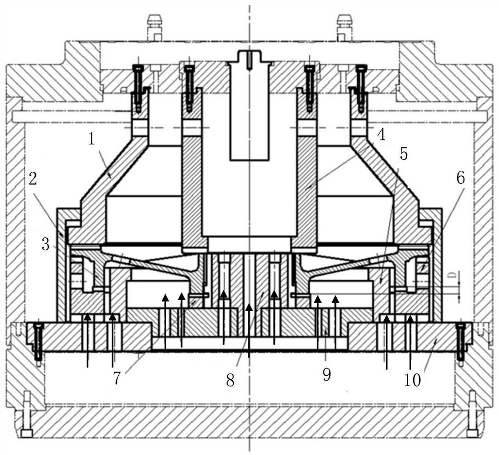
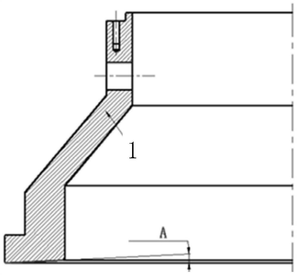
The invention discloses a combined quenching die for deformation control of a long web large face gear. The combined quenching die comprises an upper die and a lower die, wherein the upper die comprises an outer pressure ring and an inner pressure ring, the outer pressure ring is used for applying pressure to a tooth part of a face gear part, the inner pressure ring is used for applying pressure to a spline end face of the part, the lower die comprises a base, and a lower supporting ring, a large supporting pad, a small supporting pad and a positioning mandrel, wherein the lower supporting ring, a large supporting pad, a small supporting pad and a positioning mandrel are positioned on the base, the lower supporting ring is located between the base and a web of the part and used for supporting the web, the large supporting pad comprises an inner supporting platform and an outer supporting platform, the outer supporting platform is used for supporting the tooth part of the part, the inner supporting platform is used for supporting a supporting part of the part, and the small supporting pad is located between the part lower end journal part and the base and used for supporting the part lower end journal part. According to the combined quenching die for the deformation control of the long web large face gear and the heat treatment method, the quenching deformation can be effectively controlled.

Description

technical field [0001] The invention relates to the field of gear heat treatment, in particular to a combined quenching mold for large face gears with long webs and a heat treatment method. Background technique [0002] 9310 steel is a low-carbon alloy steel, which is a low-hardenability steel. After carburizing and quenching, the surface can obtain high hardness, and has excellent strength and toughness. The face gear pair has the characteristics of large reduction ratio and high transmission power, and will be popularized and applied. Due to the poor hardenability of 9310 steel, the effective thickness of the parts cannot be too large during carburizing and quenching. When making large-scale face gears, the effective thickness must be less than 18mm. Large-scale face gears with long webs with specifications greater than Ф600 are due to structural stress during carburizing and quenching. Larger distortion will occur due to the influence of thermal stress, and the elastic r...

Claims


Application Information

Patent Timeline
IPC IPC(8): C21D1/673C21D9/32C21D11/00C23C8/22
CPCC21D1/673C21D9/0062C21D9/32C21D11/00C23C8/22
Inventor 刘龙凯刘丽婷吴仡璇吴平
Owner ZHONGNAN TRANSMISSION MACHINERY FACTORY CHANGSHAAVIATION IND
Learn More